Shielding reed and rectangular connector with same

A technology for rectangular connectors and connector sockets, which is applied in the direction of connection, two-part connection devices, parts of connection devices, etc., which can solve the plastic deformation of the shielding spring I21 and the inability to reuse the shielding spring connector plug and socket housing Conductive continuity and electromagnetic shielding performance and other issues, to achieve the effect of ensuring conductive connectivity

Pending Publication Date: 2021-08-17
SHANGHAI SHENDE MEDICAL TECH CO LTD +2
View PDF0 Cites 0 Cited by
  • Summary
  • Abstract
  • Description
  • Claims
  • Application Information

AI Technical Summary

Problems solved by technology

In actual use, the misalignment of the connector plug housing 10 and the connector socket 2 may, on the one hand, easily cause the glue-fixed shielding reed I21 to detach from its adherent body, that is, the connector socket 2; on the other hand, For the rivet fixing type, it is easy to cause long-term fatigue excessive compression on the shielding reed I21 on one side of the connector socket 2, resulting in plastic deformation of the shielding reed I21; In this case, the compression contact performance of the shielding spring can no longer be used to achieve the conductive continuity and electromagnetic shielding performance of the connector plug and socket shell

Method used


Image

  • Shielding reed and rectangular connector with same
  • Shielding reed and rectangular connector with same
  • Shielding reed and rectangular connector with same

Examples


Embodiment Construction

[0037] The present invention will be described in detail below in conjunction with the accompanying drawings and specific embodiments.

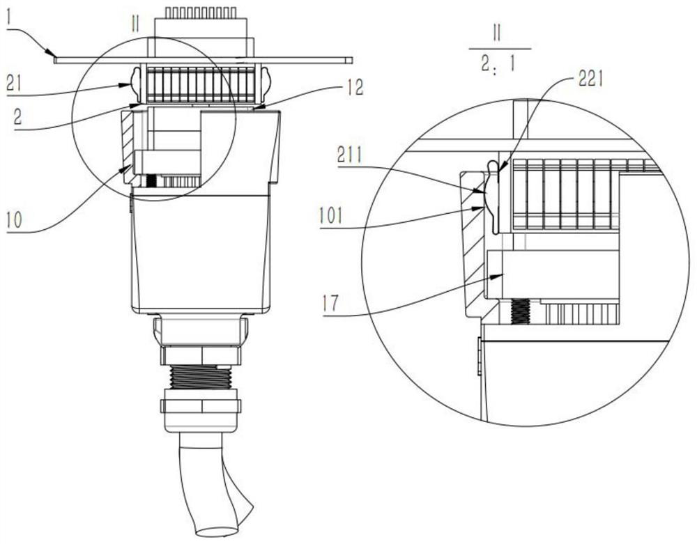
[0038] Such as figure 1 , is a schematic diagram of the structure of the existing rectangular connector. The connector socket 2 is fixed on the panel 1 by screws, and the shielding spring I21 is arranged between the connector socket 2 and the connector plug. The back glue with conduction function or the through hole for rivet fixed connection is arranged at the foot 221 to fix it on the side surface of the connector socket 2 .

[0039] During the mating process of the connector plug and the connector socket 2, the inner surface of the connector plug housing 10 forms a dynamic elastic contact with the shielding spring I21 fixed on the outside of the connector socket 2, and the protrusion 211 of the shielding spring I21 Squeezed from the inner side 101 of the connector plug housing 10, after the protrusion 211 of the shielding spring I21 is pr...


PUM


Abstract

The invention relates to a shielding reed and a rectangular connector with the shielding reed. The connector is composed of a shielding reed body and an elastic part; the shielding reed body is a rectangular ring piece and is divided into a long edge part and a short edge part, and the surface of the shielding reed body is provided with a plurality of arch-shaped protruding elastic parts which are closely arranged in the same direction. The effective conductive connectivity of the shell and the panel of the connector plug connected with the shielding reed is ensured by utilizing the elastic contact connection and the circumferential uniform and tight arrangement of the elastic part of the shielding reed; even if the plug and the socket of the connector are not plugged in an aligned manner or are plugged in a fatigue overload manner, the local elastic connection of another shielding reed in the circumferential direction of the inner side of the shell of the plug of the connector and the outer side of the socket of the connector is invalid. The axial arrangement of the shielding reeds can make up or replace effective conductive continuity between the connector plug shell and the panel, and the overall shielding function of an overall wire harness system of a shielding cable connected with the connector plug and the connector socket is achieved.

Description

technical field [0001] The invention relates to a shielding reed and a rectangular connector with the shielding reed, which is mainly used in the technical field of medical matrix connectors with high terminal density required for electromagnetic shielding. Background technique [0002] The shielded matrix connector is based on the Faraday cage principle, and uses the uniform and approximately zero-gap mating connection between the plug and the outer casing of the socket that are respectively connected to the shielding braid on the outside of the cable to realize the connection between the plug and the socket on the connector. The conductive continuity of the entire wire harness of the cable and the electromagnetic shielding performance of the shield formed by it; among them, the conductive continuity of the cable and the connector plug or socket can be realized by using conventional functional components with 360-degree shielding conduction. [0003] Matrix connectors with ...

Claims


Application Information

Patent Timeline
Patent Type & Authority Applications(China)
IPC IPC(8): H01R13/6584H01R24/00
CPCH01R13/6584H01R24/00
Inventor 田周刘自豪陶健苏志强刘文杰崔磊温家宝卢华鑫郑浩伦郭骏杰
Owner SHANGHAI SHENDE MEDICAL TECH CO LTD
Why Eureka
Try Eureka