
A wire-disconnecting device based on rapid motor maintenance

A fast, clamping mechanism technology, used in electromechanical devices, manufacturing motor generators, electrical components, etc., can solve the problems of stator damage and large load, and achieve the effect of stable clamping

Active Publication Date: 2022-06-24
浙江天工电机有限公司
View PDF13 Cites 0 Cited by
  • Summary
  • Abstract
  • Description
  • Claims
  • Application Information

AI Technical Summary

Problems solved by technology

[0004] The above-mentioned patent has the following disadvantages: it uses two claws, one hooks the motor stator, and the other hooks the coil, and uses pulling force to separate the coil from the stator. Since the coil is actually installed, pressure will be applied to both sides of its axial direction. As a result, the maximum outer diameter of the coil is much larger than the inner diameter of the stator. When pulling directly, on the one hand, it will cause a large load on the pulling, and on the other hand, using forced pulling to separate will cause damage to the stator. Therefore, further improvement is needed

Method used


Image

  • A wire-disconnecting device based on rapid motor maintenance
  • A wire-disconnecting device based on rapid motor maintenance
  • A wire-disconnecting device based on rapid motor maintenance

Examples


Embodiment 1

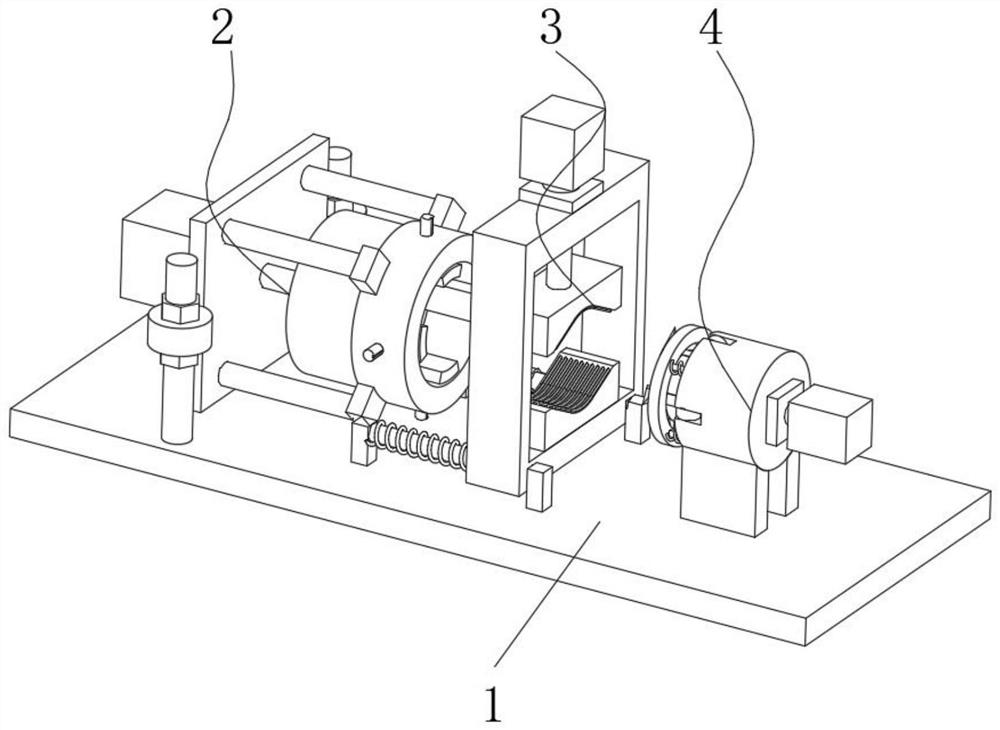
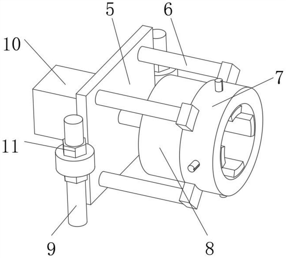
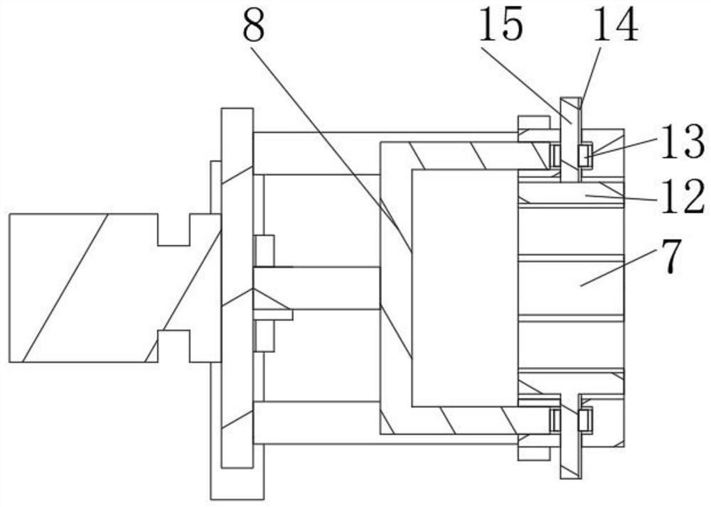
[0038] A wire removal device based on motor quick maintenance, such as Figure 1-3As shown, including a workbench 1, the top outer wall of the workbench 1 is sequentially provided with a shaping mechanism 2, a clamping mechanism 3 and a separation mechanism 4, and the shaping mechanism 2 includes a support plate 5, an outer ring 7 and an inner ring 8, Both outer walls of the support plate 5 are movably connected with lifting screws 9. The lifting screws 9 are fixed on the top outer wall of the workbench 1 by bolts. Adjust the nut 11, the outer wall of one side of the support plate 5 is fixed with the rotary motor 10 by bolts, the output shaft of the rotary motor 10 is welded to the outer wall of the axis of the inner ring 8, and the outer ring 7 is fixedly connected to the support plate 5 through four support rods 6 , the outer ring 7 is slidingly connected with the inner ring 8, and the inner wall of the outer ring 7 is connected with four shrinking screws 15 through threads....

Embodiment 2

[0042] A wire removal device based on rapid motor maintenance, in order to solve the problem of coil detachment device; this embodiment makes the following improvements on the basis of Embodiment 1, such as Image 6 As shown, the outer wall of the separating hook 30 is integrally formed with a shrinking inclined surface protrusion 29, and the inner wall of the limit ring 24 is rotatably connected with a shrinking roller 28 corresponding to the position of the shrinking inclined surface protrusion 29; when the hydraulic cylinder 23 is in the shrinking state, After it pulls the coil out of the stator, when the shrinking slope protrusion 29 reaches the shrinking roller 28, its limiting action will rotate the four separating hooks 30 closer to each other, so that they are separated from the coil, so that the coil can be more closely connected with the device. A good separation completes the collection of coils.

Embodiment 3

[0044] A wire removal device based on rapid motor maintenance, in order to further solve the separation problem between the coil and the device; this embodiment makes the following improvements on the basis of Embodiment 2, such as Figure 6-8 As shown, a blocking ring 27 is slidably connected to one side of the outer wall of the limit ring 24 through four sliding rods 26 . It is a tapered type, and the outer side of the tapered shape is an inclined surface, and the inner side is a flat surface; since the four separation hooks 30 in the embodiment 2 are contracted, the coil is affected by gravity and will still hang on the separation hook 30 at the top, Manual separation is also required. In this embodiment, the blocking ring 27 is provided. When the separating hook 30 is contracted to the other side of the coil and contacts the blocking ring 27, the retracting roller 28 cooperates with the retracting slope protrusion 29. During the process of approaching each other, on the o...


PUM


Abstract

The invention discloses a dismantling device based on rapid motor maintenance, which relates to the technical field of motor maintenance; in order to solve the problem of large tensile load and damage to the stator; it specifically includes a workbench, and the top outer wall of the workbench is sequentially provided with a shaping mechanism, a clip A holding mechanism and a separation mechanism, the shaping mechanism includes a support plate, an outer ring and an inner ring, the outer walls of both sides of the support plate are movably connected with lifting screws, the lifting screws are fixed on the top outer wall of the workbench by bolts, and the lifting screws Adjusting nuts are threaded on both sides of the joint with the support plate, a rotating motor is fixed on one side of the support plate by bolts, and the output shaft of the rotating motor is welded to the outer wall at the axis of the inner ring. The invention can shape and shrink the coil, and the shrinking speeds of the four shaping plates are exactly the same, so that the shrinking direction of the coil is all in the radial direction of the stator, which is relatively regular, and facilitates subsequent separation from the stator.

Description

technical field [0001] The invention relates to the technical field of motor maintenance, in particular to a wire removal device based on rapid motor maintenance. Background technique [0002] Existing motors have different winding methods according to different models. When the windings of the motor are burned out, it is difficult to remove the windings of the motor. [0003] After searching, the Chinese patent publication number is CN207459933U, which discloses a motor quick repair wire removal tool, including a first installation plate, an elastic part, a collection box, a second installation plate, a clamping mechanism, a wire removal mechanism and a support mechanism; the second mounting plate is fixed on the top of the first mounting plate along the vertical direction; the collection box is fixed on the top of the first mounting plate through elastic parts, and is located on one side of the second mounting plate; the clamping mechanism is fixed on the first mounting pl...

Claims


Application Information

Patent Timeline
Patent Type & Authority Patents(China)
IPC IPC(8): H02K15/00
CPCH02K15/0006
Inventor 李柏万
Owner 浙江天工电机有限公司
Learn More