Puncture part pressing device used after cerebrovascular interventional operation

An interventional surgery and cerebrovascular technology, applied in the field of medical appliances, can solve the problem of inconvenient observation of the recovery of the puncture site and other problems

Active Publication Date: 2021-08-20
NANYANG SECOND GENERAL HOSPITAL
View PDF6 Cites 1 Cited by
  • Summary
  • Abstract
  • Description
  • Claims
  • Application Information

AI Technical Summary

Problems solved by technology

[0003] The purpose of the present invention is to provide a puncture site presser after cerebrovascular interventional surgery to solve the problem of inconvenient observation of the rehabilitation of the puncture site proposed in the background technology

Method used


Image

  • Puncture part pressing device used after cerebrovascular interventional operation
  • Puncture part pressing device used after cerebrovascular interventional operation
  • Puncture part pressing device used after cerebrovascular interventional operation

Examples


Embodiment 1

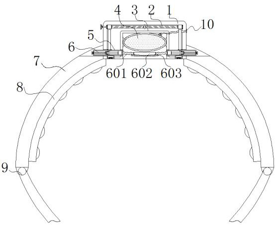
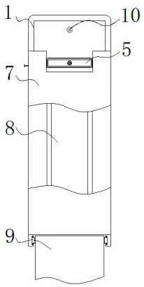
[0030] Example 1: See Figure 1-8 , a puncture site presser after cerebrovascular interventional surgery, comprising a fixing box 1, a clamping plate 7 and a tightening belt 9, the lower ends of both sides of the fixing box 1 are equipped with clamping plates 7, and the bottom ends of the clamping plate 7 are provided with tightening straps With 9, the upper end inside the fixed box 1 is provided with an adjustment structure 2;

[0031] An airbag box 3 is installed in the middle of the bottom end of the fixed box 1, and a spherical bag 4 is arranged on the upper end of the airbag box 3, and a connecting pipe 10 extending to the outside of the fixed box 1 is installed on the upper end of one side of the spherical bag 4 through a flexible hose. And the inner bottom of the fixed box 1 around the airbag box 3 is provided with a compression observation structure;

[0032] The lower ends of both sides of the airbag box 3 are provided with adjustment plates 5 extending to the outsid...

Embodiment 2

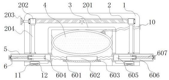
[0038] Embodiment 2: The adjustment structure 2 includes a positive and negative screw rod 201, a rod block 202, an adjustment handle 203, a vertical plate 204 and a scale 205, and the positive and negative screw rod 201 is connected to the middle position of the top inside the fixed box 1 by lateral rotation. And the positive and negative screw rod 201 side is installed with the adjustment handle 203 that extends to the outside of the fixed box 1, and the inside of the fixed box 1 on both sides of the positive and negative screw rod 201 is screwed with a rod block 202, and the bottom end of the rod block 202 Vertical boards 204 are installed vertically, the bottom of the vertical boards 204 is fixedly connected to the top side of the adjustment board 5, and a scale 205 is provided at the middle position of the top of the adjustment board 5 on the side of the vertical boards 204;

[0039] The distance between one side of the vertical plate 204 and one side of the airbag box 3 i...

Embodiment 3

[0041] Embodiment 3: The hemostatic structure 6 includes elastic strips 601, Velcro 602, hemostatic cotton pads 603, connecting rods 604, sliding blocks 605, H-shaped reserved grooves 606, threaded rods 607, hemostatic handles 608 and threaded blocks 609, H The type reserved grooves 606 are all horizontally set at the middle position inside the adjusting plate 5, and the middle positions on one side of the H-shaped reserved grooves 606 are connected with a threaded rod 607 which is horizontally rotated, and one side of the threaded rod 607 is installed with a The hemostatic rocker 608 on the outside of the adjustment plate 5, and the inner side of the H-shaped reserved groove 606 on the threaded rod 607 are threadedly connected with a threaded block 609, and the two ends of the threaded block 609 are installed with the other end extending to the inside of the H-shaped reserved groove 606. The connecting rod 604 on the side, and the other side of the H-shaped reserved groove 606...


PUM


Abstract

The invention discloses a puncture part pressing device used after cerebrovascular interventional operation, and relates to the technical field of medical instruments. The puncture part pressing device comprises a fixing box, clamping plates and lacing belts; the clamping plates are installed at the lower ends of the two sides of the fixing box; the lacing belts are arranged at the bottom ends of the clamping plates;, an adjusting structure is arranged at the upper end of the interior of the fixing box; an air bag box is mounted in the middle of the bottom end in the fixing box; a spherical bag is arranged at the upper end in the air bag box; a communicating pipe extending to the outside of the fixing box is mounted at the upper end of one side of the spherical bag through a hose, and a pressing observation structure is arranged at the bottom end in the fixing box around the air bag box; and adjusting plates extending out of the fixing box are arranged at the lower ends of the two sides of the air bag box. By arranging a pressing pad and a heat exchange groove, cold compress or hot compress is achieved, the healing effect is improved, the blood flowing rate near a puncture part can be slowed down, then the bleeding phenomenon caused by the fact that a wound is not healed can be avoided, and medical staff can conveniently observe the wound healing condition.

Description

technical field [0001] The invention relates to the technical field of medical appliances, in particular to a presser for puncture sites after cerebrovascular interventional operations. Background technique [0002] After searching, the Chinese Patent Authorization Announcement No. CN110101428A, announced on August 09, 2019, discloses a device for pressing the puncture site after cerebrovascular intervention. The hole is sealed and fixedly connected with a connecting pipe, and the left and right sides of the air intake shell are provided with through holes through which the one-way valve one and the one-way valve two are respectively fixedly connected. The outlet of the one-way valve two is connected to the The left end of the pipe is fixedly connected, the inner wall of the air intake shell is slidably connected with a piston, and the upper surface of the piston is fixedly connected with a pressure rod". In view of the phenomenon of bleeding at the puncture site due to the...

Claims


Application Information

Patent Timeline
IPC IPC(8): A61B17/135
CPCA61B17/135A61B2017/12004
Inventor 刘清华
Owner NANYANG SECOND GENERAL HOSPITAL
Why Eureka
Try Eureka