Cleaning and disinfecting device for medical apparatus and instruments
A technology for cleaning and sterilizing medical equipment, applied in the field of medical equipment, can solve the problems of waste of resources, roughness, and inconcentration of washing, and achieve the effect of flexible movement
- Summary
- Abstract
- Description
- Claims
- Application Information
AI Technical Summary
Problems solved by technology
Method used
Image
Examples
Embodiment 1
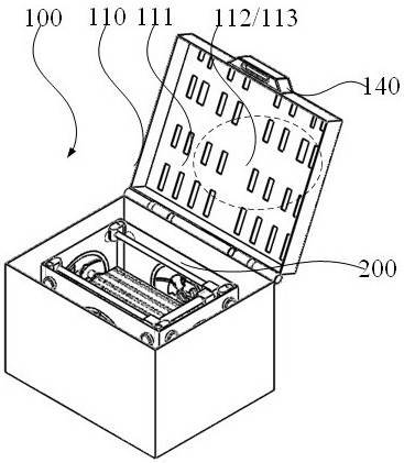
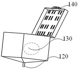
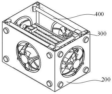
[0027] This embodiment provides a cleaning and disinfection device 400 for medical equipment, such as Figure 1~Figure 7 As shown, the device includes a cleaning and disinfection box body 100, an inner container 200, a lifting device 300 and a cleaning and disinfection device 400, wherein:
[0028] The cleaning and disinfection box body 100 includes a discharge part 120 and a storage part 130 , one end of the discharge part 120 is fixedly connected to the lower end of the cleaning and disinfection box body 100 , and the storage part 130 is located at the side of the cleaning and disinfection box body 100 .
[0029] The inner container 200 is a box structure with an open upper end and is detachably connected to the inner cavity of the cleaning and disinfection box body 100. The peripheral side and the lower end of the inner container 200 are provided with a through hole 230 in a combined shape, and the lower end of the inner container 200 is A slideway 220 and at least four fix...
Embodiment 2
[0038] The difference between this embodiment and embodiment 1 is that, as Figure 4 with Figure 5 As shown, the lifting bracket 310 includes at least two sliders 311, a first base bar 312, a second base bar 313, a first connecting rod 314 and a second connecting rod 315, wherein: the two sliders 311 are embedded in Any slideway 220, and transmission connection between two sliders 311, any two sliders 311 are rotationally connected with one end of the first basic rod 312 and the second basic rod 313, the first basic rod 312 and the second basic rod 313 The midpoint of the base bar 313 is rotatably connected, and the other end of the first base bar 312 and the second base bar 313 are rotatably connected with one end of the first connecting bar 314 and the second connecting bar 315, and the first connecting bar 314 and the second The other end of the connecting rod 315 is rotatably connected with the shaft of the flip clamping bracket 320 .
[0039] With the above-mentioned t...
Embodiment 3
[0044] The difference between this embodiment and embodiment 1-2 is that, as Figure 8 As shown, the cleaning nozzle 440 includes a lamp tube sterilizing device 441, an annular through hole 442, a first pipeline 443, a second pipeline 444, a first circuit 445, a first solenoid valve 446 and a second solenoid valve 447, wherein: The lamp tube sterilizing device 441 is fixedly connected to one end of the cleaning nozzle 440, the annular channel is located on the peripheral side of the lamp tube sterilizing device 441, and one end of the annular channel 442 is respectively connected to one end of the first pipe 443 and the second pipe 444 through a three-way joint. connection, the middle section of the first pipeline 443 is connected with the first solenoid valve 446, the middle section of the second pipeline 444 is connected with the second solenoid valve 447, the other end of the first pipeline 443 and the second pipeline 444 are connected with the storage part 130 pipeline, and...
PUM
 Abstract
Description
Claims
Application Information
 - R&D
- Intellectual Property
- Life Sciences
- Materials
- Tech Scout
- Unparalleled Data Quality
- Higher Quality Content
- 60% Fewer Hallucinations
Browse by: Latest US Patents, China's latest patents, Technical Efficacy Thesaurus, Application Domain, Technology Topic, Popular Technical Reports.
© 2025 PatSnap. All rights reserved.Legal|Privacy policy|Modern Slavery Act Transparency Statement|Sitemap|About US| Contact US: help@patsnap.com


