Eureka AIR delivers breakthrough ideas for toughest innovation challenges, trusted by R&D personnel around the world.

Weight-bearing exoskeleton bearing device

An exoskeleton and back technology, applied in the field of exoskeleton, can solve the problems of reducing the effect of upper extremity exoskeleton, inconvenient use, and increasing the force

Active Publication Date: 2021-08-20
CHONGQING UNIV OF TECH
View PDF15 Cites 5 Cited by
  • Summary
  • Abstract
  • Description
  • Claims
  • Application Information

AI Technical Summary

Problems solved by technology

[0004] When the existing upper extremity exoskeleton is used together with the lower extremity exoskeleton, the upper extremity exoskeleton and the lower extremity exoskeleton are fixedly connected, so the upper extremity exoskeleton and lower extremity exoskeleton Exoskeletons are often inconvenient to disassemble and can only be used at the same time. For example, when the human body only needs to use the upper extremity exoskeleton to carry heavy loads, the upper extremity exoskeleton cannot be easily disassembled and used with the lower extremity exoskeleton, resulting in the use of It is inconvenient. At the same time, when the upper extremity exoskeleton is assisting the human body to carry heavy objects, since the human body will reciprocate in the vertical direction when walking, the heavy objects will also reciprocate in the vertical direction at this time. The energy generated during reciprocating motion will increase the force on the shoulders and waist of the human body, which will greatly reduce the weight-bearing capacity of the human body and reduce the assisting effect of the upper extremity exoskeleton

Method used


Image

  • Weight-bearing exoskeleton bearing device
  • Weight-bearing exoskeleton bearing device
  • Weight-bearing exoskeleton bearing device

Examples


Embodiment Construction

[0044] The present invention will be further described below in conjunction with the accompanying drawings and embodiments.

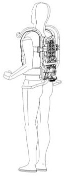
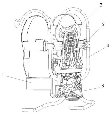
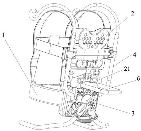
[0045] as attached figure 1 to attach Figure 5 As shown, a load-bearing exoskeleton carrying device includes a back assembly 2, a waist assembly 3, a storage assembly, and a strap waist seal assembly 1 for wearing the load-bearing exoskeleton carrying device on the upper limbs of a human body. The upper end of the back assembly 2 is connected to the strap The waist seal assembly 1 is connected to the corresponding position on the back of the human body, the lower end of the back assembly 2 is connected to the waist assembly 3, and the storage assembly is detachably connected to the waist assembly 3 or the back assembly 2. The shock mechanism, the waist plate is connected with the strap waist seal assembly 1 at the corresponding position, the waist adjustment shock absorbing mechanism includes a rotating connector 31, and support rods 33 symmetrically ...


PUM


Abstract

The invention discloses a weight-bearing exoskeleton bearing device which comprises a back assembly, a waist assembly, a storage assembly and a strap and waist belt assembly. The upper end of the back assembly is connected with the strap and waist belt assembly and the position corresponding to the back of a human body; the lower end of the back assembly is connected with the waist assembly; the storage assembly is detachably connected onto the waist assembly or the back assembly; the waist assembly comprises a waist flitch plate and a waist adjusting and damping mechanism; the waist flitch plate is connected with the strap and waist belt assembly; the waist adjusting and damping mechanism comprises a rotary connecting piece and supporting rods symmetrically arranged on the two axial sides of the rotary connecting piece; one end of each supporting rod is rotationally connected onto the rotary connecting piece through a first longitudinal rotating piece; the other end of each supporting rod is detachably connected with an external lower limb exoskeleton; and a supporting spring is further arranged between the two supporting rods. According to the scheme, the bearing capacity of the exoskeleton can be improved, and meanwhile, independent use or matched use with the lower limb exoskeleton is facilitated through the modular design.

Description

technical field [0001] The invention relates to the technical field of exoskeleton, in particular to a load-bearing exoskeleton carrying device. Background technique [0002] As a wearable auxiliary device, the exoskeleton organically combines human intelligence and the "physical energy" of the exoskeleton to enhance the function of the human body. [0003] Exoskeletons mainly include upper extremity exoskeletons and lower extremity exoskeletons. Upper extremity exoskeletons are mainly used to wear on human upper limbs to provide assistance for human upper limbs to carry or upper limbs to carry heavy objects. Lower limb exoskeletons are mainly used to wear on human lower limbs to exercise for human lower limbs. Provide assistance. The mechanical structure of the exoskeleton is the basis of the whole system. It is combined with the human body, not only to support the load-bearing role, but also to transmit motion and force. There is a kinematic coupling between man and machi...

Claims


Application Information

Patent Timeline
IPC IPC(8): B25J9/00
CPCB25J9/0006
Inventor 黎波宁强刘家红周梦刘闵超李玉霞覃磊胡东森秦金宝
Owner CHONGQING UNIV OF TECH
Why Eureka
Eureka Blog
Learn More