
Method for correcting influence of blade end rounding on flow

A blade and flow technology, which is applied in the field of axial flow turbines, can solve the problems such as the rounding flow change at the end of the blade that cannot be solved.

Active Publication Date: 2021-08-20
HARBIN TURBINE +1
View PDF9 Cites 0 Cited by
  • Summary
  • Abstract
  • Description
  • Claims
  • Application Information

AI Technical Summary

Problems solved by technology

[0005] In order to overcome the problem that the engineering method in the prior art cannot solve the influence of the flow change caused by the rounding of the blade end and correct the height of the working part of the blade, it further provides a correction method for the influence of the rounding of the blade end on the flow rate

Method used


Image

  • Method for correcting influence of blade end rounding on flow
  • Method for correcting influence of blade end rounding on flow
  • Method for correcting influence of blade end rounding on flow

Examples


specific Embodiment approach 1

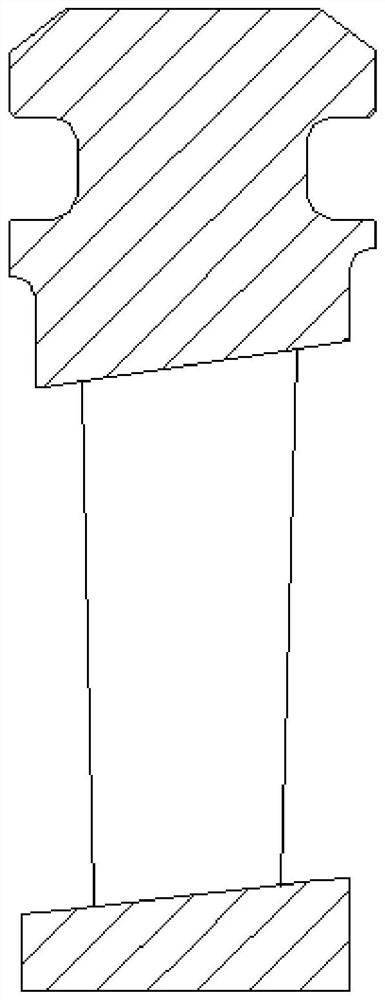
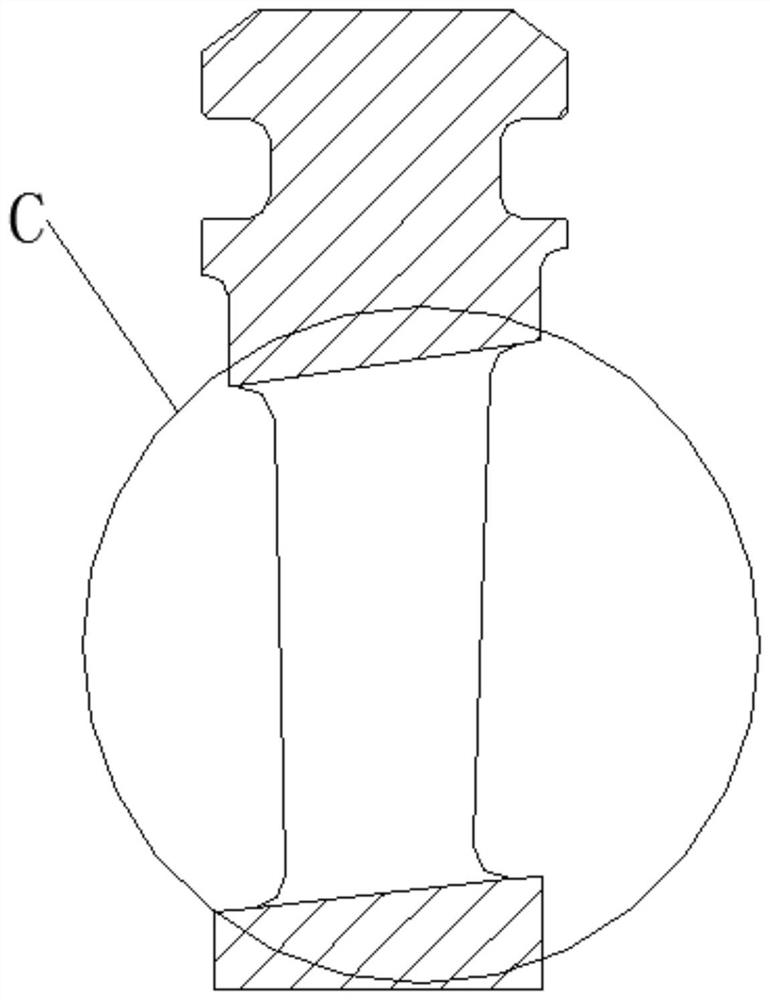
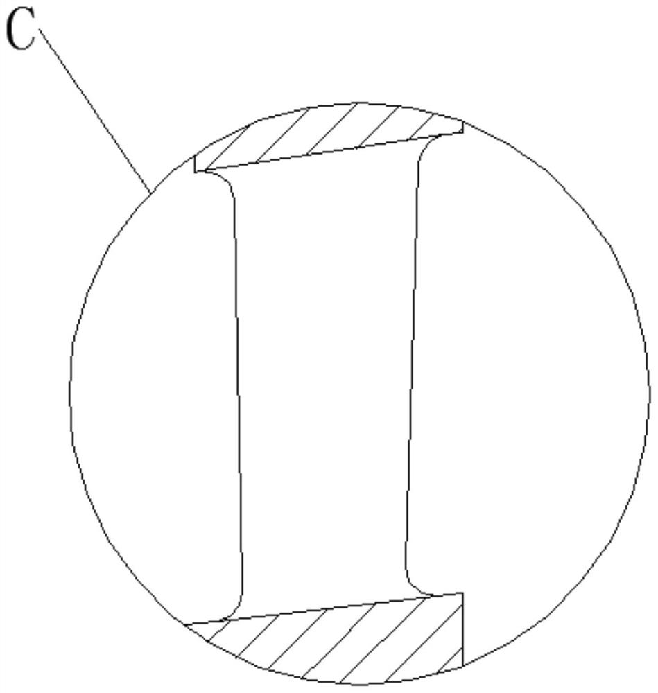
[0062] Specific implementation mode one: combine Figure 1 to Figure 16 Describe this embodiment, a method for correcting the influence of blade end rounding on flow in this embodiment, which includes the following steps:

[0063] Step 1. According to the relative size of the throat width O of the blade end and the radius R of the blade rounding, determine the calculation formula used for the correction:

[0064] When the airfoil throat width O at the end of the blade is greater than or equal to 2R, this is the case A, and the calculation formula used for the correction is

[0065] A 01 =2(R 2 -πR 2 / 4) = 0.4292R 2 (1);

[0066] When the airfoil throat width O at the end of the blade is less than 2R, this is case B, and the calculation formula used for correction is

[0067]

[0068] Step 2. Calculate the reduction value A of the flow area b :

[0069] Since the blade rounding is relatively small in value relative to the height of the working part of the blade, it ...

specific Embodiment approach 2

[0095] Specific implementation mode two: combination Figure 4 to Figure 6 Describe this embodiment. In step 2 of this embodiment, when the root rounding area is case A, the area is A 1 The formula for calculating is,

[0096] A 1 =2(R 1 2 -πR 1 2 / 4) = 0.4292R 1 2 (8);

[0097] In step 2, when the root rounding area is case B, the area is A 2 ;

[0098]

[0099] Others are the same as the first embodiment.

specific Embodiment approach 3

[0100] Specific implementation mode three: combination Figure 8 to Figure 10 Describe this embodiment. In step 2 of this embodiment, when the top rounded area is case A, the area is A 3 ;

[0101] A 3 =2(R 3 2 -πR 3 2 / 4) = 0.4292R 3 2 (10);

[0102] In step 2, when the top rounded area is case B, the area is A 4 :

[0103]

[0104] Others are the same as those in Embodiment 1 or 2.


PUM


Abstract

The invention discloses a method for correcting influence of blade end rounding on flow. The invention particularly relates to an axial-flow turbine. The method aims to solve the problems that an engineering method in the prior art cannot solve the influence of flow change caused by rounding of the end of the blade and cannot correct the height of a working part of the blade. The method comprises the following steps: determining a calculation formula adopted for correction according to the relative size of a blade profile throat width O at the end part of the blade and a blade rounding radius R; calculating a through-flow area reduction value Ab; calculating a total through-flow area A0 of the blade without considering rounding by adopting an integration method; calculating an area correction coefficient delta A; calculating an efficiency correction coefficient delta b according to a full-three-dimensional CFD loss library; calculating a total correction coefficient delta; calculating the partial height delta L of the corrected blade; calculating the corrected blade height as the original blade height; repeating the steps 1-8, and when the result of the correction coefficient is convergent, obtaining the final corrected blade working part height. The invention is applied to the field of axial-flow turbines.

Description

technical field [0001] The invention relates to the field of axial flow turbines, in particular to a method for correcting the influence of blade end rounding on flow. Background technique [0002] With the advancement of technology, the design of axial flow turbines is changing from "coarse" to "fine". This transformation makes the flow control requirements higher, especially the flow control of the first few stages is very critical, and it needs to be between turbine output and efficiency. Make a balance: if the flow is too large, the efficiency of the equipment will be low; if the flow is too small, the output of the equipment will be insufficient. The first few stages of the axial flow turbine have the smallest height of the working part, and the rounding of the end has a great influence. If it is not considered, it will cause efficiency and output problems. Taking a blade with a height of 20mm in the working part and a radius of R3mm in the root tip as an example, the ...

Claims


Application Information

Patent Timeline
IPC IPC(8): F01D5/14F01D21/00F01D25/00
CPCF01D5/141F01D5/147F01D21/003F01D25/00Y02P70/50
Inventor 刘云锋马天吟翁振宇刘长春李宇峰马义良熊继龙王健潘春雨关淳刘鑫李昂徐洪峰
Owner HARBIN TURBINE
Learn More