
Cooling device for high-temperature wind tunnel model

A cooling device and wind tunnel technology, which is applied in household refrigeration devices, measuring devices, applications, etc., can solve problems such as affecting the accuracy of wind tunnel tests, introducing additional error sources to test data, and adversely affecting the development of wind tunnel tests.

Active Publication Date: 2021-08-20
中国空气动力研究与发展中心超高速空气动力研究所
View PDF16 Cites 1 Cited by
  • Summary
  • Abstract
  • Description
  • Claims
  • Application Information

AI Technical Summary

Problems solved by technology

After the test is completed, the temperature of the model body will also be very high, and the high temperature of the model body will have an adverse effect on the development of subsequent wind tunnel tests
[0003] One is: if the temperature of the model body cannot be lowered to normal temperature before the next wind tunnel test is carried out, then the initial conditions of different test trips will be different, which will introduce additional error sources to the test data and affect the accuracy of the wind tunnel test. Spend;
[0004] The second is: if the temperature of the model body is naturally cooled to normal temperature, it will take more than several hours, which seriously affects the test efficiency and is not conducive to the effective use of wind tunnel resources;
[0005] The third is: the high temperature of the model body will bring potential safety hazards. Since the current wind tunnels use manual methods to replace the parts or states of the test model, if the temperature of the model body is too high, the staff may be scalded

Method used


Image

  • Cooling device for high-temperature wind tunnel model
  • Cooling device for high-temperature wind tunnel model
  • Cooling device for high-temperature wind tunnel model

Examples


Embodiment 1

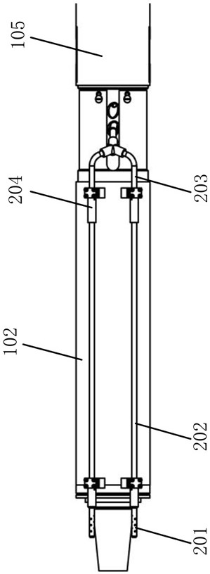
[0031] With the incoming flow of the wind tunnel as the front, the model of the cooling device used for the high temperature wind tunnel model of the present invention is fixed on the middle bracket of the high temperature wind tunnel in the form of a rod balance and a tail support. The cooling device includes a balance rod protection assembly, and Includes a cold spray assembly that fits inside the model to cool it down;

[0032] Such as figure 1 As shown, the pole-type balance assembly 101 includes a pole-type balance 1011 and a balance pole 1012 fixedly connected from front to back. A channel is arranged on the top, and an air-cooled intake pipe 203 connected with an external high-pressure air source is installed in the channel;

[0033] Such as figure 2 As shown, the balance pole protection assembly includes a balance heat shield 102 and a pole heat shield 105; the balance heat shield 102 is set on the pole balance 1011 in the pole balance assembly 101, and the pole hea...


PUM


Abstract

The invention discloses a cooling device for a high-temperature wind tunnel model. The model is fixed on a middle support of the high-temperature wind tunnel in a rod type balance and tail supporting mode, and the cooling device comprises a balance supporting rod protection assembly and a cold spraying assembly installed in the model and used for cooling the model. The balance supporting rod protection assembly comprises a balance heat shield and a support rod heat shield. The cold spraying assembly comprises an air cooling spray head, an air cooling quick-insertion straight pipe, an air cooling air inlet pipe and an air cooling pipe connector. High-pressure cooling gas of a high-pressure gas source flows in from an air-cooling gas inlet pipe in an inner cavity of the balance supporting rod, flows out of the balance supporting rod, flows through an air-cooling pipe connector and an air-cooling fast-inserting straight pipe which are installed on the outer surface of a balance heat shield, is sprayed out from an air-cooling spray head, and cools the model and the rod type balance in an inner cavity of the model. The cooling device is simple in structure, flexible in use mode and convenient for model disassembly, the temperature of a model body after a test can be quickly reduced, a test error source caused by initial wall temperature difference is eliminated, and the quality of test data is ensured.

Description

technical field [0001] The invention belongs to the field of hypersonic wind tunnel test equipment, and in particular relates to a cooling device for a high-temperature wind tunnel model. Background technique [0002] The high temperature wind tunnel is characterized by a particularly high total flow temperature, which will lead to a high temperature rise of the high temperature wind tunnel model throughout the test process. Taking the Mach number 7 wind tunnel test state of the HB-2 model as an example, the maximum total temperature of the incoming flow in the wind tunnel is about 2000K. During the 30s blowing test, the temperature rise of the stagnation point area of ​​the model head and the tail skirt area reaches 550K ℃ or more. After the test is completed, the temperature of the model body will be very high, and the high temperature of the model body will have an adverse effect on the subsequent wind tunnel test. [0003] One is: if the temperature of the model body c...

Claims


Application Information

Patent Timeline
IPC IPC(8): G01M9/04G01M9/08F25D1/00
CPCG01M9/04G01M9/08F25D1/00
Inventor 郭雷涛谢飞石罡崔炜栋王佳明吴有生
Owner 中国空气动力研究与发展中心超高速空气动力研究所
Learn More