Finite element modeling method for self-aligning roller bearing

A technology of self-aligning roller bearings and modeling methods, applied in special data processing applications, instruments, electrical digital data processing, etc., can solve problems such as changes in stress transmission paths, affecting finite element strength analysis results, and loss of self-aligning effects , to achieve the effect of good model convergence performance

Active Publication Date: 2021-08-20
CSIC CHONGQING HAIZHUANG WINDPOWER EQUIP
View PDF3 Cites 0 Cited by
  • Summary
  • Abstract
  • Description
  • Claims
  • Application Information

AI Technical Summary

Problems solved by technology

[0003] The problem existing in the modeling method in the prior art is that when the inner and outer rings of the bearing have relative rotation, axial movement and bending deformation, the bearing will transmit the bending moment, and partly lose the self-aligning effect, resulting in the change of the stress transmission path and affecting the strength of the finite element analysis results

Method used


Image

  • Finite element modeling method for self-aligning roller bearing
  • Finite element modeling method for self-aligning roller bearing

Examples


Embodiment Construction

[0019] Embodiments of the technical solutions of the present invention will be described in detail below in conjunction with the accompanying drawings. The following examples are only used to illustrate the technical solutions of the present invention more clearly, and therefore are only examples, rather than limiting the protection scope of the present invention.

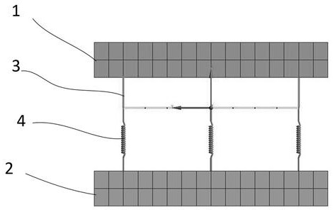
[0020] see Figure 1~2 As shown, the present invention provides a spherical roller bearing finite element modeling method, including the following steps:

[0021] S1. Create the structure and unit type of the finite element three-dimensional model of the bearing, establish the finite element analysis model of the inner and outer rings of the bearing, and ensure that the corresponding joint lines of the inner and outer rings of the bearing pass through the bearing center;

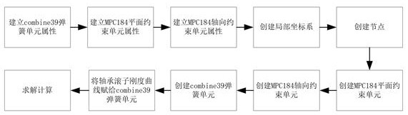
[0022] S11. Establish spring unit properties, plane constrained unit properties and axial constrained unit properties, create a local three-dim...


PUM


Abstract

The invention provides a finite element modeling method for a self-aligning roller bearing. The method comprises the following steps: S1, creating a structure and a unit type of a bearing finite element three-dimensional model, establishing a bearing inner and outer ring finite element analysis model, and ensuring that a connecting line of corresponding contact points of the bearing inner and outer rings passes through the center of the bearing; S2, determining corresponding nodes of each group of units forming the roller on the inner ring and the outer ring of the bearing, and establishing intermediate nodes between the corresponding nodes of the inner ring and the outer ring of the bearing; S3, establishing an axial constraint unit between a corresponding node and the intermediate node of the bearing outer ring; S4, establishing plane constraint units and spring units between the corresponding nodes and the intermediate nodes of the bearing inner ring; and S5, assigning the rigidity curve parameter of the bearing roller to the spring unit, and carrying out solution calculation. When the method is used for modeling, when the inner ring and the outer ring of the bearing relatively rotate or axially float, the combined unit does not transmit bending moment, the force transmission characteristic of the bearing can be correctly reflected, and the model convergence performance of the modeling mode is better.

Description

technical field [0001] The invention relates to the technical field of wind power generation, in particular to a finite element modeling method for a spherical roller bearing. Background technique [0002] During the design and development of large-scale wind turbines, it is necessary to check the strength of components with finite element elements to ensure the ultimate and fatigue strength of components under complex loads. Finite Element Analysis (FEA, Finite Element Analysis) uses mathematical approximation methods to simulate real physical systems (geometry and load conditions). In this process, it is necessary to simplify the analysis model and remove features that have little influence on the calculation results. structure, and ensure that the force conduction path remains unchanged to ensure the accuracy of finite element calculations. Among the various components of large V-shaped wind turbines, spherical roller bearings are usually used as main bearings. The spher...

Claims


Application Information

Patent Timeline
Patent Type & Authority Applications(China)
IPC IPC(8): G06F30/17G06F30/23G06F119/14
CPCG06F30/17G06F30/23G06F2119/14Y02T90/00
Inventor 解轲江鹏韩佳谭俊宫伟杨微
Owner CSIC CHONGQING HAIZHUANG WINDPOWER EQUIP
Why Eureka
Try Eureka