
Torsion-controllable lumbar vertebra turning-around device

A technique of lumbar spine and torsion, applied in the direction of fixator, etc., can solve the problems of affecting the operation of screw removal, difficult to control the size of torque, sliding of lumbar screws, etc., so as to avoid the effect of sliding or damage.

Inactive Publication Date: 2021-08-24
AIR FORCE MEDICAL CENT PLA
View PDF5 Cites 2 Cited by
  • Summary
  • Abstract
  • Description
  • Claims
  • Application Information

AI Technical Summary

Problems solved by technology

In the prior art, when installing the lumbar screw, it is necessary to turn the lumbar screw through a U-turn device to fix the lumbar screw. However, during the twisting process, since the torque is not easy to control, it is easy to cause the lumbar screw to slip or slip. The condition of the damage will affect the later nail removal operation

Method used


Image

  • Torsion-controllable lumbar vertebra turning-around device
  • Torsion-controllable lumbar vertebra turning-around device
  • Torsion-controllable lumbar vertebra turning-around device

Examples


Embodiment Construction

[0030] In order to make the purposes, technical solutions and advantages of the embodiments of the present application clearer, the technical solutions in the embodiments of the present application will be clearly and completely described below in conjunction with the drawings in the embodiments of the present application. Obviously, the described embodiments It is a part of the embodiments of this application, not all of them. The components of the embodiments of the application generally described and illustrated in the figures herein may be arranged and designed in a variety of different configurations.

[0031] Accordingly, the following detailed description of the embodiments of the application provided in the accompanying drawings is not intended to limit the scope of the claimed application, but merely represents selected embodiments of the application. Based on the embodiments in this application, all other embodiments obtained by persons of ordinary skill in the art w...


PUM


Abstract

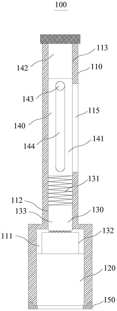
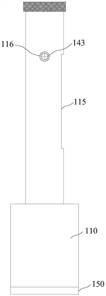
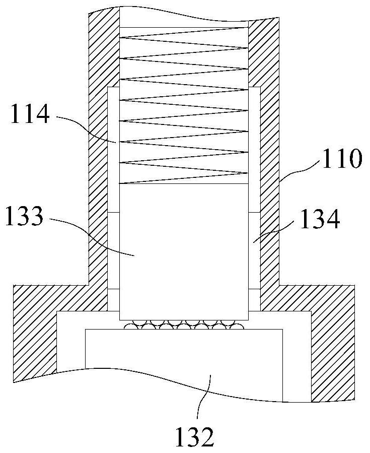
The invention relates to the field of medical instruments, in particular to a torsion-controllable lumbar vertebra turning-around device. The lumbar vertebra turning-around device comprises a main body, a rotating drum, a torsion structure and a limiting structure; the main body is provided with an inner cavity and an opening communicated with the inner cavity; the rotating drum is rotatably accommodated in the inner cavity and is positioned at one end, close to the opening, of the inner cavity; the axis of the rotating drum coincides with the axis of the main body; the torsion structure comprises an elastic piece, a first end face gear and a second end face gear. The first end face gear is connected with the rotary drum, the second end face gear is contained in the inner cavity in a sliding mode along the axis of the main body, and the first end face gear is meshed with the second end face gear; the limiting structure is connected with the main body and located at the end, away from the opening, of the main body. The elastic piece is contained in the inner cavity, and the two ends of the elastic piece abut against the limiting structure and the second end face gear respectively. The limiting structure is used for adjusting the compression amount of the elastic piece. According to the torsion-controllable lumbar vertebra turning-around device, the phenomenon that the lumbar vertebra screw slips during installation can be avoided.

Description

technical field [0001] The present application relates to the field of medical devices, in particular to a lumbar head-turning device with controllable torque. Background technique [0002] At present, when the lumbar spine is diseased or injured, in order to treat or further recover, the surgery needs to perform fixed surgery on the lumbar spine, and it is common to install lumbar screws. In the prior art, when installing the lumbar screw, it is necessary to turn the lumbar screw through a U-turn device to fix the lumbar screw. However, during the twisting process, since the torque is not easy to control, it is easy to cause the lumbar screw to slip or slip. The condition of damage will affect the later nail removal operation. Contents of the invention [0003] The present application provides a lumbar head-turning device with controllable torque to improve the above problems. [0004] The present invention is specifically as follows: [0005] A lumbar head-turning dev...

Claims


Application Information

Patent Timeline
IPC IPC(8): A61B17/92
CPCA61B17/92
Inventor 杜俊杰陈宇飞曹艳杰栾冠楠薛静厉晓杰
Owner AIR FORCE MEDICAL CENT PLA
Learn More