Finish machining device for aluminum casting shell of motor

A motor and aluminum casting technology, which is applied in the direction of grinding drive devices, metal processing equipment, manufacturing tools, etc., can solve the problems of inconsistent specifications, increased labor costs, and poor grinding effects of grinding devices, so as to avoid displacement and improve precision. The effect of processing efficiency and quality

Active Publication Date: 2021-08-24
徐州汇易容金属科技有限公司
View PDF9 Cites 0 Cited by
  • Summary
  • Abstract
  • Description
  • Claims
  • Application Information

AI Technical Summary

Problems solved by technology

[0003] At present, in order to improve the heat dissipation effect of the motor and reduce the weight of the motor, aluminum casting shells are used. Most of the conventional aluminum casting shells of electric motors are molded by integral casting. After the shell is formed, a large number of burrs generally remain on the surface, which is relatively rough. It is not conducive to spraying protective coatings, so the shell needs to be polished, and there are generally a large number of cooling fins on the outer wall of the conventional motor shell, and the specifications are inconsistent. Grinding, which greatly reduces the finishing efficiency of the motor casing, and the conventional grinding device can only be used for finishing the aluminum casting casing of a single size motor, and the function is relatively single. At the same time, when installing the aluminum casting casing of the motor, manual labor is required. Manual alignment and fixing are time-consuming and labor-intensive, increasing labor costs, which brings inconvenience to the finishing of the aluminum casting housing of the motor

Method used


Image

  • Finish machining device for aluminum casting shell of motor
  • Finish machining device for aluminum casting shell of motor
  • Finish machining device for aluminum casting shell of motor

Examples


Embodiment Construction

[0026] In order to make the technical means, creative features, goals and effects achieved by the present invention easy to understand, the present invention will be further elaborated below in conjunction with specific drawings; it should be noted that, in the case of no conflict, the embodiments and Features in the embodiments can be combined with each other.

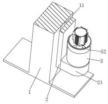
[0027] refer to figure 1 , a motor aluminum casting shell finishing device, including a main bracket 1, one side of the main bracket 1 is rotatably connected to a No. Playing the role of support and fixation, the No. 1 rotating shaft 11 rotates under the drive of the external driving device, which can drive the rotating frame 2 to rotate.

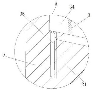
[0028] refer to figure 2 , the two ends of the rotating frame 2 away from the No. 1 rotating shaft 11 are provided with installation blocks 21, and the No. 1 hydraulic cylinder 22 is arranged in the installation blocks 21, and the installation direction of the No. 1 hydraulic cy...


PUM


Abstract

The invention relates to the field of motor manufacturing, in particular to a finish machining device for the aluminum casting shell of a motor. The finish machining device comprises a main support, one side of the main support is rotationally connected with a first rotating shaft, a rotating frame is arranged at the end, away from the main support, of the first rotating shaft, and mounting blocks are arranged at the two ends of the side, away from the first rotating shaft, of the rotating frame. First hydraulic cylinders are arranged in the mounting blocks, the mounting directions of the first hydraulic cylinders in the two mounting blocks are opposite, the output ends of the first hydraulic cylinders penetrate through the mounting blocks and are fixedly provided with pressing rods, the ends, away from the first hydraulic cylinders, of the pressing rods are provided with pressing blocks of conical structures, and the ends, away from the pressing rods, of the pressing blocks are provided with inserting rods. The inserting rods on the two pressing blocks are distributed in a staggered mode, and adjusting grooves are formed in the ends, away from the pressing blocks, of the inserting rods. According to the finish machining device, a formed motor aluminum casting shell can be rapidly clamped and fixed, and adjustment can be conducted according to the height of the motor aluminum casting shell.

Description

technical field [0001] The invention relates to the field of motor manufacturing, in particular to a device for finishing the aluminum casting shell of a motor. Background technique [0002] The motor is a device that converts electrical energy into mechanical energy; it uses a energized coil to generate a rotating magnetic field and acts on the rotor to form a magnetoelectric force; the motor is divided into DC motor and AC motor according to the power supply used. The motor in the power system is large Part of it is an AC motor, and it can also be a synchronous motor or an asynchronous motor. [0003] At present, in order to improve the heat dissipation effect of the motor and reduce the weight of the motor, aluminum casting shells are used. Most of the conventional aluminum casting shells of electric motors are molded by integral casting. After the shell is formed, a large number of burrs generally remain on the surface, which is relatively rough. It is not conducive to ...

Claims


Application Information

Patent Timeline
Patent Type & Authority Applications(China)
IPC IPC(8): B24B31/10B24B31/12B24B41/06B24B47/06
CPCB24B31/10B24B31/12B24B41/06B24B47/06
Inventor 杜卫东
Owner 徐州汇易容金属科技有限公司
Why Eureka
Try Eureka