Valve body crack welding repair fixing clamp

A welding repair and fixture fixing technology, applied in welding equipment, auxiliary welding equipment, welding/cutting auxiliary equipment, etc., can solve problems such as low efficiency, increase the cost of valve body use, welding repair deviation, etc., to avoid deviation, The effect of lowering the repair efficiency and maintaining stability

Active Publication Date: 2022-02-15
江苏德邦流体控制有限公司
View PDF8 Cites 3 Cited by
  • Summary
  • Abstract
  • Description
  • Claims
  • Application Information

AI Technical Summary

Problems solved by technology

[0003] During the use of the valve body, the valve body often has cracks due to factors such as external force impact or excessive internal pressure. These cracks will affect the strength of the valve body and bring hidden dangers to the use of the valve, so the valve body has cracks. After that, it cannot continue to be used, and directly returning the cracked valve body to the furnace for rebuilding will directly increase the use cost of the valve body and is not conducive to environmental protection. Therefore, most of the existing valve body crack treatment methods are welded Solder is filled into the gaps of the cracks to repair the cracks. At present, most of the cracks on the valve body are welded and repaired by manually supporting the valve body to keep the cracks on the valve body in a horizontal state. Therefore, two operators are often required to cooperate with the operation. The efficiency of repairing the cracks on the valve body in this way is relatively low and the labor cost is high, and manual support cannot guarantee the stability of the valve body. It is easy to cause deviation when welding and repairing cracks on the valve body, which brings inconvenience to the welding repair of cracks on the valve body

Method used


Image

  • Valve body crack welding repair fixing clamp
  • Valve body crack welding repair fixing clamp
  • Valve body crack welding repair fixing clamp

Examples


Embodiment Construction

[0027] In order to make the technical means, creative features, goals and effects achieved by the present invention easy to understand, the present invention will be further elaborated below in conjunction with specific drawings; it should be noted that, in the case of no conflict, the embodiments and Features in the embodiments can be combined with each other.

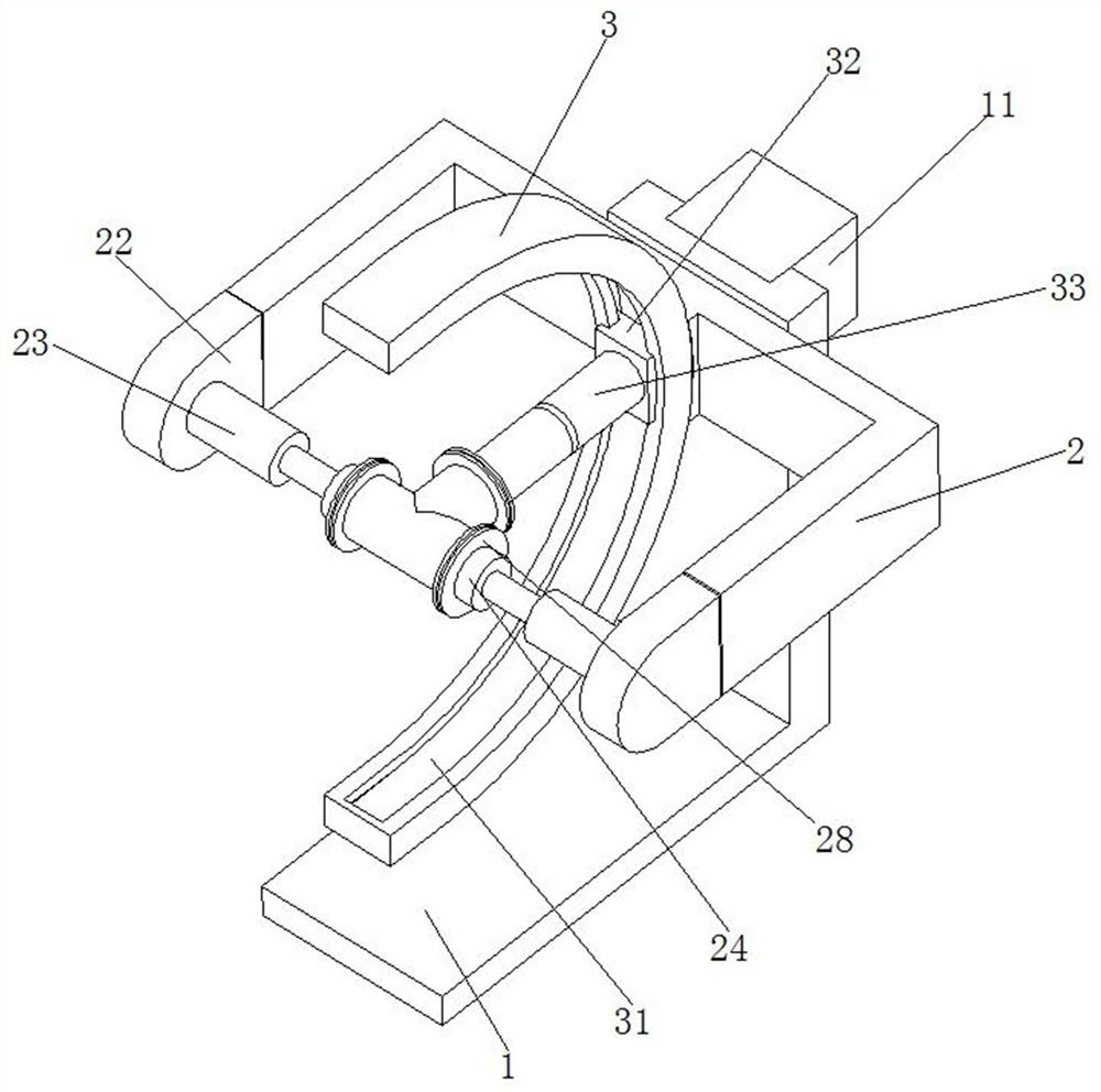
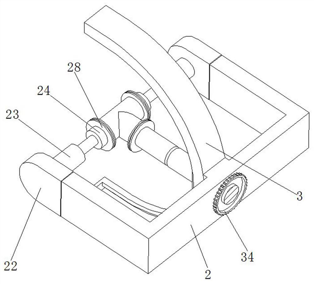
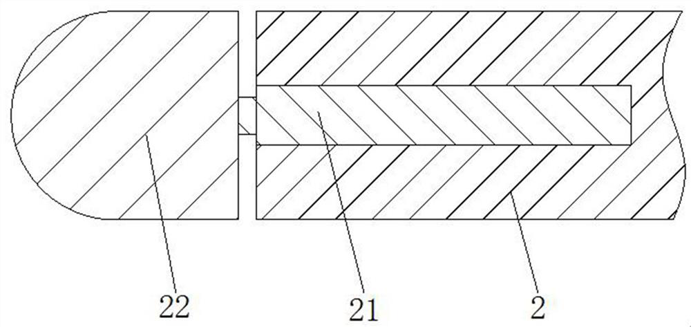
[0028] refer to figure 1 and image 3 , a valve body crack welding repair fixing fixture, including a support frame 1, the support frame 1 is an L-shaped structure, a rotating motor 11 is fixedly installed on the support frame 1, and a connecting frame with a concave structure is fixedly installed on the output end of the rotating motor 11 2. Two spring pull rods 21 are installed symmetrically and fixedly in the connecting frame 2. The telescoping ends of the two spring pull rods 21 all pass through the connecting frame 2 and are fixedly installed with a connecting block 22. The side of the two connecting blocks 22 c...


PUM


Abstract

The invention relates to the technical field of valve body repair fixing clamps, in particular to a valve body crack welding repair fixing clamp which comprises a supporting frame, the supporting frame is of an L-shaped structure, a rotating motor is fixedly installed on the supporting frame, a connecting frame of a concave structure is fixedly installed at the output end of the rotating motor, and spring pull rods are symmetrically and fixedly installed in the connecting frame. The telescopic ends of the two spring pull rods penetrate through the connecting frame and are fixedly provided with connecting blocks, and first air cylinders are rotationally installed on the sides, close to each other, of the two connecting blocks. An existing valve body crack treatment mode is low in efficiency and high in labor cost, and the stability of a valve body cannot be guaranteed through manual supporting. A valve body with cracks can be rapidly clamped and fixed, multi-angle adjustment can be conducted on the valve body according to the positions of the cracks, the problem that an existing repairing mode is low in repairing efficiency is solved, and the labor cost is reduced.

Description

technical field [0001] The invention relates to the technical field of a valve body repair fixing fixture, in particular to a valve body crack welding repair fixing fixture. Background technique [0002] The valve body is a major part of the pipeline. The valve body adopts different mechanical manufacturing methods according to its applicable pressure level, such as casting and forging. [0003] During the use of the valve body, the valve body often has cracks due to factors such as external force impact or excessive internal pressure. These cracks will affect the strength of the valve body and bring hidden dangers to the use of the valve, so the valve body has cracks. After that, it cannot continue to be used, and directly returning the cracked valve body to the furnace for rebuilding will directly increase the use cost of the valve body and is not conducive to environmental protection. Therefore, most of the existing valve body crack treatment methods are welded Solder is...

Claims


Application Information

Patent Timeline
Patent Type & Authority Applications(China)
IPC IPC(8): B23K37/04
CPCB23K37/0435
Inventor 李娜罗社新罗寅东
Owner 江苏德邦流体控制有限公司
Why Eureka
Try Eureka