
Heat dissipation protective shell for packaging optical fiber device

A technology of optical fiber devices and protective shells, applied in the field of heat dissipation protective shells, can solve the problems of poor heat dissipation effect of optical fiber devices, fragile optical fibers, pulling at interfaces, etc.

Inactive Publication Date: 2021-08-24
扬州港信光电科技有限公司
View PDF5 Cites 0 Cited by
  • Summary
  • Abstract
  • Description
  • Claims
  • Application Information

AI Technical Summary

Problems solved by technology

[0003] However, there are certain deficiencies in the packaging of optical fiber devices in the past. After the packaging of optical fiber devices in the past, the heat dissipation and heat preservation effect of the optical fiber device is extremely poor. The poor heat dissipation effect of the optical fiber device will reduce the service life of the optical fiber device itself, and The connection between the optical fiber and the device is not well protected, the optical fiber is fragile, and the interface is easily pulled

Method used


Image

  • Heat dissipation protective shell for packaging optical fiber device
  • Heat dissipation protective shell for packaging optical fiber device
  • Heat dissipation protective shell for packaging optical fiber device

Examples


Embodiment Construction

[0035] The following will clearly and completely describe the technical solutions in the embodiments of the present invention with reference to the accompanying drawings in the embodiments of the present invention. Obviously, the described embodiments are only some, not all, embodiments of the present invention. Based on the embodiments of the present invention, all other embodiments obtained by persons of ordinary skill in the art without making creative efforts belong to the protection scope of the present invention.

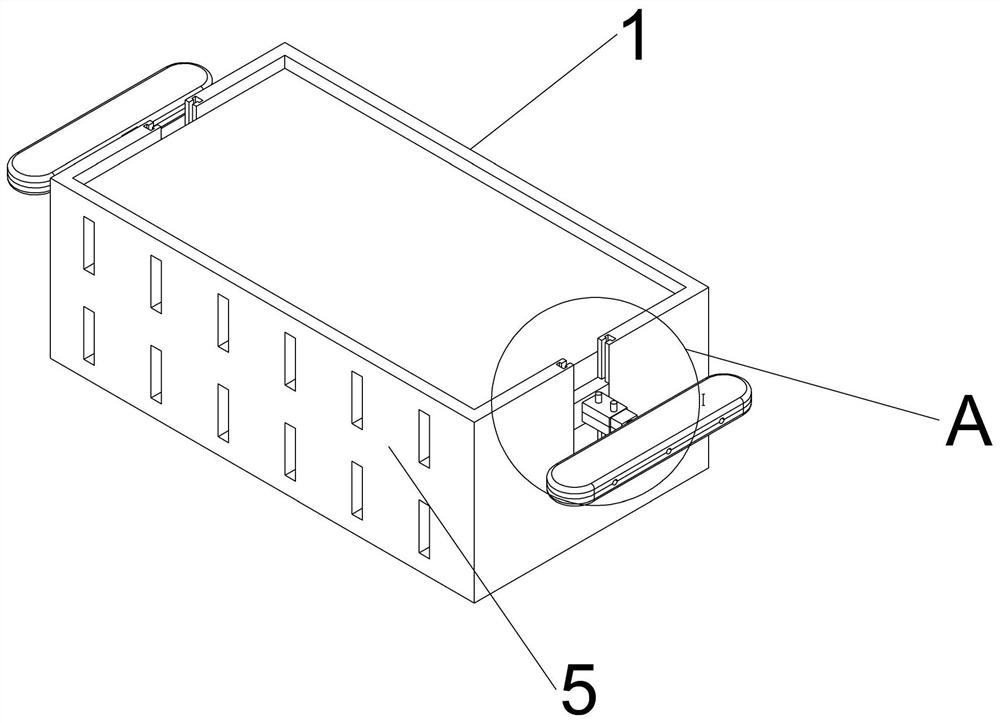
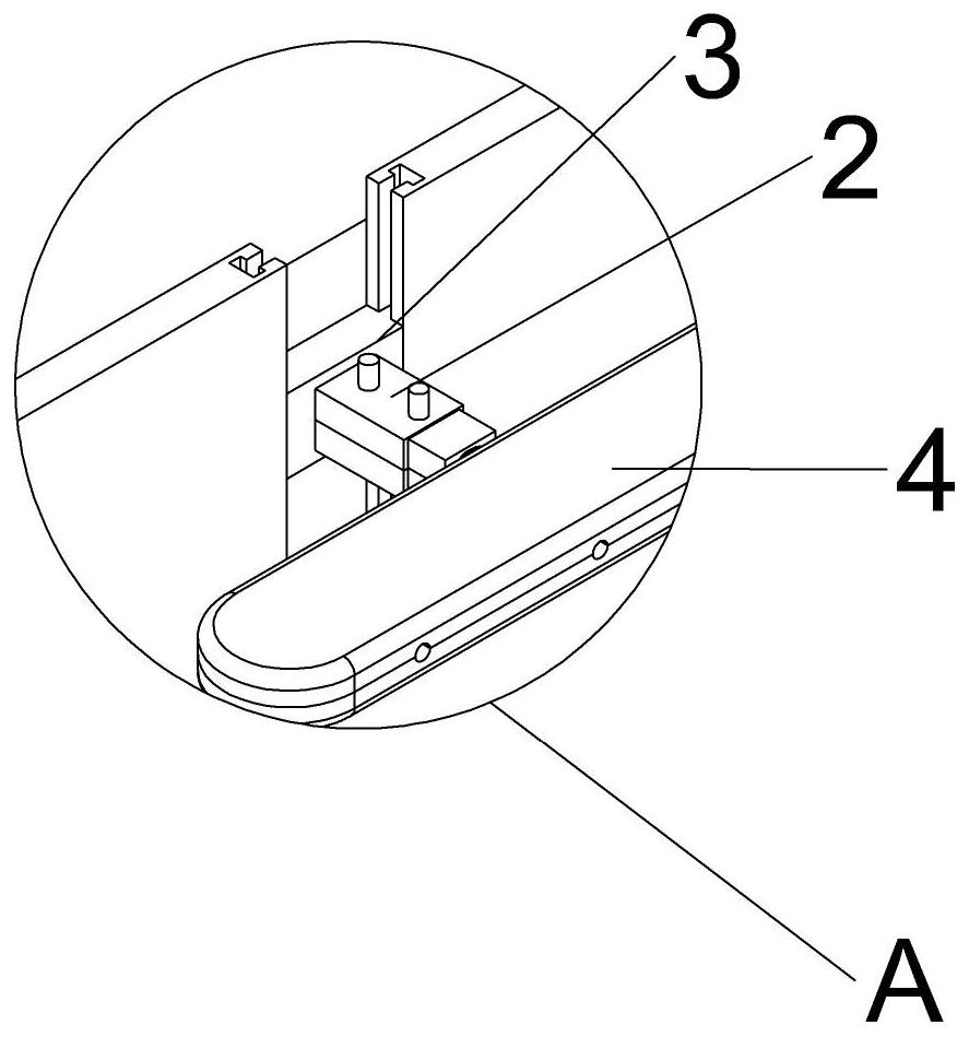
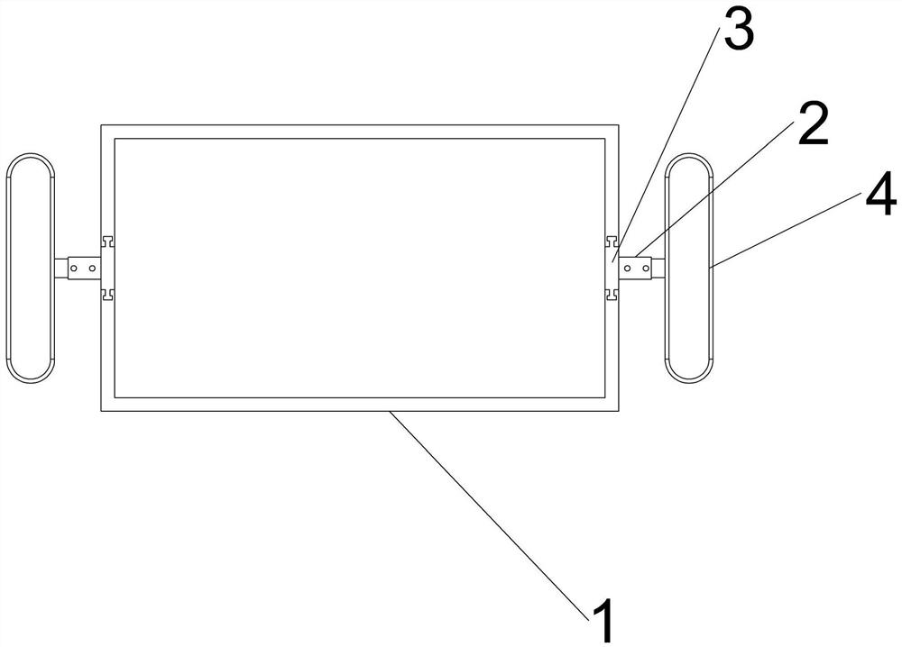
[0036] see Figure 1-14 , a packaged heat dissipation protective case for optical fiber devices, comprising a heat dissipation device 1, an interface protection device 2 is installed at both ends of the heat dissipation device 1, a slider 3 is provided at the front end of the interface protection device 2, and a protection disk is provided at the rear end of the interface protection device 2 4. A cooling box 5 is installed between the interface protection devi...


PUM


Abstract

The invention relates to the technical field of optical fiber devices, and discloses a heat dissipation protective shell for packaging an optical fiber device, which comprises a heat dissipation device, interface protection devices mounted at two ends of the heat dissipation device, sliding blocks arranged at the front ends of the interface protection devices, protection discs arranged at the rear ends of the interface protection devices, and a heat dissipation box mounted between the interface protection devices; fixing bolts are arranged at the two side ends of the sliding blocks, clamps are arranged in the fixing bolts, concave grooves are formed in the rear ends in the sliding blocks, a first disc and a second disc are arranged at the top end and the bottom end of each protection disc respectively, clamping grooves are formed in the inner side walls of the first discs and the second discs, and top columns are arranged on the edges of the bottom faces of the first discs. According to the heat dissipation protective shell for packaging the optical fiber device, the clamping grooves are formed between the inner sides of the first discs and the inner sides of the second discs, the effect of embedding an optical fiber and other wires can be achieved through the clamping groove, the effect of effectively packaging and protecting the optical fiber can be achieved, the corner of the internal clamping grooves arearc-shaped, and the situation that the optical fiber is folded and damaged is prevented.

Description

technical field [0001] The invention relates to the technical field of optical fiber devices, in particular to a packaged heat dissipation protective case for optical fiber devices. Background technique [0002] The unit that converts, connects and controls the optical path in the optical fiber transmission system, also known as optical passive devices, mainly includes optical connectors, optical couplers, optical switches, optical attenuators, multiplexers and demultiplexers, etc., packaged , is the process of assembling the integrated circuit into the final product of the chip. Simply put, it is to put the bare integrated circuit chip produced by the foundry on a substrate that acts as a load-bearing function, lead out the pins, and then fix and package it into a chip. overall. [0003] However, there are certain deficiencies in the packaging of optical fiber devices in the past. After the packaging of optical fiber devices in the past, the heat dissipation and heat prese...

Claims


Application Information

Patent Timeline
Patent Type & Authority Applications(China)
IPC IPC(8): G02B6/44
CPCG02B6/4446G02B6/4436
Inventor 袁纪文邓孟中杜运波
Owner 扬州港信光电科技有限公司
Learn More