
A chain arm saw electrical control system

An electrical control system and chain saw technology, applied in the direction of electrical program control, general control system, control/adjustment system, etc., can solve problems affecting equipment production efficiency, rich functions, poor upgradeability, waste of resources, etc., to achieve The effect of shortening the time for troubleshooting, improving work productivity, and avoiding waste of resources

Active Publication Date: 2022-05-20
泉州华大超硬工具科技有限公司
View PDF0 Cites 0 Cited by
  • Summary
  • Abstract
  • Description
  • Claims
  • Application Information

AI Technical Summary

Problems solved by technology

[0002] The current track-type chain arm cutting machine, its control system adopts the combination control of conventional low-voltage electrical components, does not have programmable functions, so the circuit is complex and cumbersome, and the functions are rich and scalable.
In addition, all current track-type arm-type sawing machines do not have feed compensation, and all have the problem of cutting dead angles, which causes troubles for on-site construction and wastes resources.
[0003] Moreover: the chain sawing machine circuit control system currently used in mines is mainly controlled by conventional buttons and instrument electrical components. It is easy to accumulate dust or rust, causing failure and affecting the production efficiency of the equipment

Method used


Image

  • A chain arm saw electrical control system
  • A chain arm saw electrical control system
  • A chain arm saw electrical control system

Examples


Embodiment Construction

[0033] The following will be combined with the accompanying drawings and embodiments to elaborate on the embodiments of the present invention, whereby the present invention how to apply technical means to solve technical problems, and to achieve a technical effect of the realization process can be fully understood and implemented. It should be noted that, as long as it does not constitute a conflict, the various embodiments of the present invention and the various features in each embodiment may be combined with each other, and the resulting technical solutions are within the scope of the present invention.

[0034] At the same time, in the following description, for the purpose of interpretation and elaboration of many specific details, to provide a thorough understanding of the embodiments of the present invention. However, to those skilled in the art will appreciate, the present invention may be implemented without the specific details herein or in a particular manner described...


PUM


Abstract

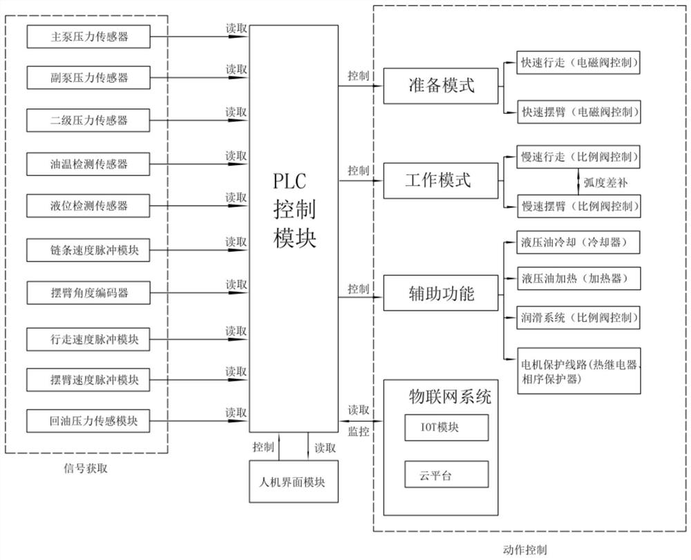
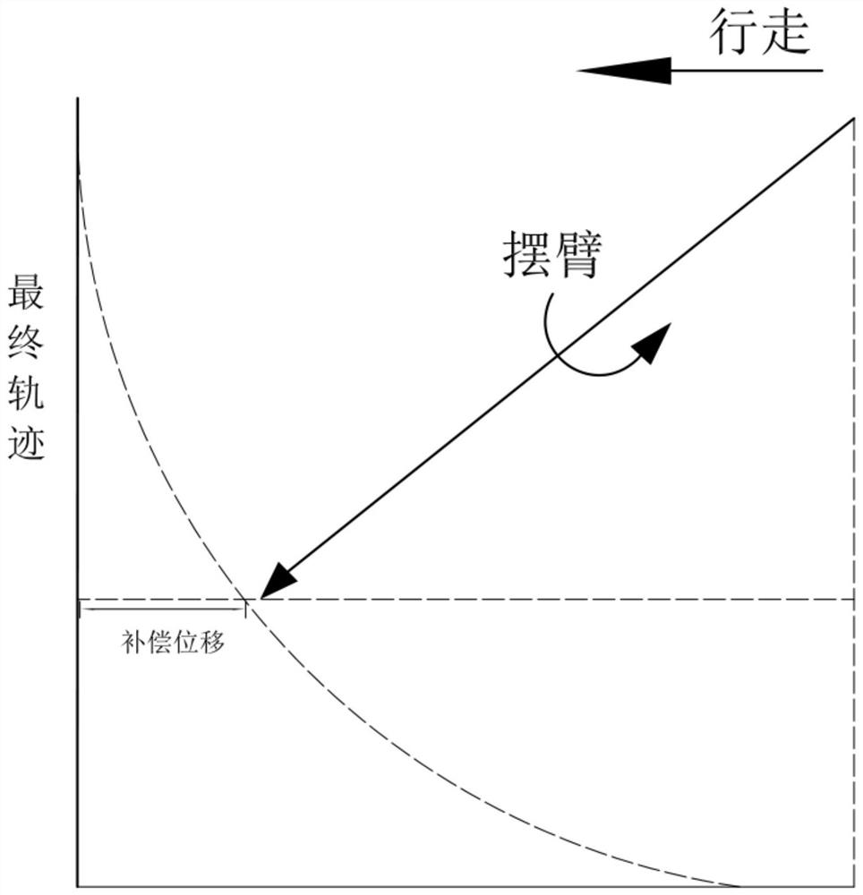
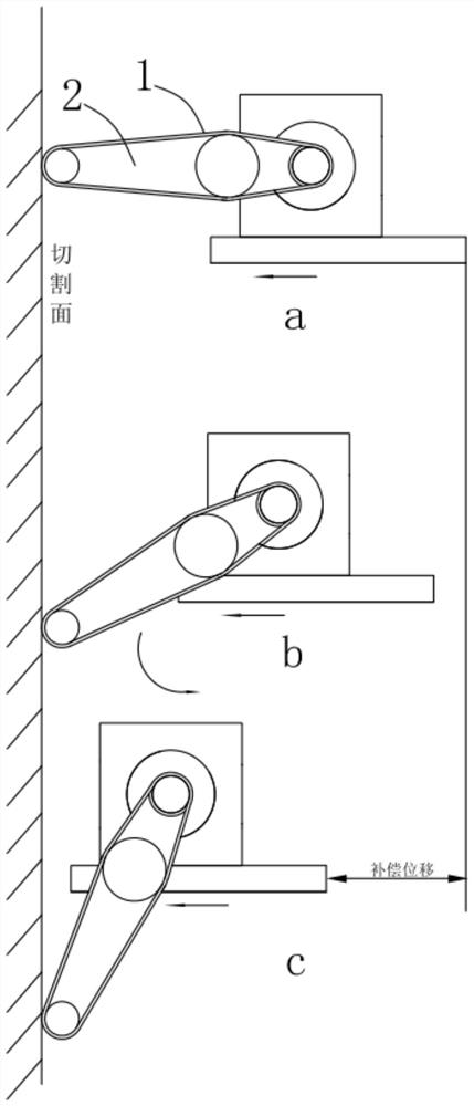
The invention discloses an electrical control system for a chain arm saw, which relates to the field of electrical control systems. The electrical control system includes: a PLC control module, a chain speed pulse module electrically connected to the PLC control module, a swing arm angle encoder, and a walking speed pulse module. Module, swing arm speed pulse module and human-machine interface module, through the pulse signal induced by the chain speed pulse module, swing arm angle encoder, walking speed pulse module and swing arm speed pulse module, and under the logic operation of the PLC control module , calculate the linear velocity value of the chain and chain arm saw walking and the angular velocity value of the chain arm swing, and control the walking of the chain arm saw and the swing action of the chain arm through the PLC control module, provide compensation displacement, and control the chain arm saw to walk at a slow speed During the slow swing cutting process, the chain arm is always in contact with the cutting surface, and the chain arm realizes no dead angle feeding, which solves the dead angle problem in the stone cutting process, improves the stone yield, and avoids the waste of resources.

Description

Technical field [0001] The present invention relates to the field of electrical control systems, specifically referring to a chain arm saw electrical control system. Background [0002] The current orbital chain arm cutting machine, its control system adopts conventional low-voltage electrical components combination control, does not have programmable functions, so the circuit is complex and cumbersome, rich in functions, and upgradeable. In addition, all the current orbital arm sawing machines, there is no tool compensation, there is a problem of cutting dead angles, causing trouble to on-site construction, but also causing waste of resources. [0003] Moreover: the current chain sawing machine circuit control system used in mines is mainly controlled by conventional buttons and instrument electrical components, and the control function simply displays a single data, and the stone mine dust is large, the water vapor is heavy, and the button electrical components are easy to accu...

Claims


Application Information

Patent Timeline
Patent Type & Authority Patents(China)
IPC IPC(8): G05B19/414
CPCG05B19/4147G05B2219/34013
Inventor 吴建李波叶和贵沈金斌
Owner 泉州华大超硬工具科技有限公司
Learn More