
Surface finishing equipment after valve body casting

A technology of casting and rear surface, which is applied in the direction of metal processing equipment, other manufacturing equipment/tools, manufacturing tools, etc., can solve the problems of lower production efficiency, shaking of the valve body left and right, and inaccurate cutting of the cutting position, so as to improve production Efficiency, accurate cutting and grinding, and the effect of improving accuracy

Active Publication Date: 2021-10-26
新沂特瑞斯机械设备有限公司
View PDF7 Cites 0 Cited by
  • Summary
  • Abstract
  • Description
  • Claims
  • Application Information

AI Technical Summary

Problems solved by technology

[0003] However, the following problems may be encountered in the surface finishing process after the valve body is cast and formed: 1. When the valve body is cut off the sprue, the structure of the valve body itself leads to unstable fixation, resulting in the valve body being cut during cutting. Shake left and right, resulting in inaccurate cutting of the cutting position, affecting the quality of valve body casting
[0004] 2. The distance between the cutting position of the traditional valve body and the placement position of the valve body is fixed, so that when cutting valve bodies of different sizes, the cutting depth cannot be adjusted according to the needs, and the pouring must be done with a file after cutting. The mouth is reprocessed, which increases the labor intensity of the workers and reduces the production efficiency

Method used


Image

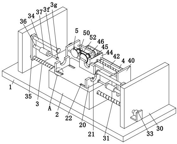
  • Surface finishing equipment after valve body casting
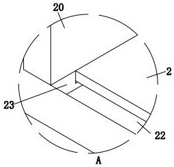
  • Surface finishing equipment after valve body casting
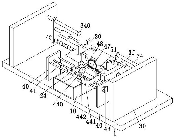
  • Surface finishing equipment after valve body casting

Examples


Embodiment Construction

[0031] Embodiments of the present invention will be described below with reference to the drawings. In this process, in order to ensure the clearness and convenience of the description, we may exaggerate the size of the width or constituent elements of the middle line.

[0032] In addition, the terms in the following are defined based on the functions in the present invention, and can be different depending on the user, the user's intention or convention. Therefore, these terms are defined based on the entire contents of this specification.

[0033] like Figures 1 to 7As shown, a valve body is cast, a rear surface finishing treatment apparatus, including a bottom plate 1, a table 2, a fixing mechanism 3, a resection mechanism 4, and a grinding mechanism 5, and the upper end surface of the bottom plate 1 is mounted 2, The upper end surface of the bottom plate 1 is provided with a fixing mechanism 3 and a resection mechanism 4, and the resection mechanism 4 is located on the rear si...


PUM


Abstract

The invention relates to a valve body surface finishing equipment after casting and molding, which includes a bottom plate, a workbench, a fixing mechanism, a cutting mechanism and a grinding mechanism. Compared with the cutting mechanism, the cutting mechanism is located on the rear side of the fixing mechanism, and the cutting mechanism is provided with a grinding mechanism. The fixing mechanism adopted in the present invention is directly inserted into the left and right ports of the valve body through an arc-shaped clamping plate for fixing, avoiding the valve body The gate shakes left and right when cutting, which improves the accuracy of the cutting position of the gate of the valve body. At the same time, the positions of the cutting mechanism and the grinding mechanism can be adjusted, and the position is adjusted according to the size of the valve body. It avoids the phenomenon that the cutting depth cannot be adjusted according to the needs and the sprue gate is processed again, which causes the labor intensity of the workers to increase, thereby improving the production efficiency.

Description

Technical field [0001] The present invention relates to the field of rear surface finishing techniques of valve body casting, and more particularly to a valve body casting processed post-surface finishing equipment. Background technique [0002] The valve is used to open and close the line, control flow, adjust, and control the parameters (temperature, pressure, and flow) of the transport medium (temperature, pressure, and flow), the valve is also controlled components in the fluid delivery system, with cutout, adjustment, flow, to prevent Function such as countercurrent, regulator, shunt, or overflow pressure, the valve for fluid control systems, from the simplest shutoff valve to the various valves used in extremely complex automatic control systems, the varieties and specifications are quite a wide variety, and the valves are available. The flow of various types of fluids such as air, water, steam, various corrosive media, mud, oil, liquid metal, and radioactive medium, and th...

Claims


Application Information

Patent Timeline
Patent Type & Authority Patents(China)
IPC IPC(8): B24B9/04B24B27/02B24B55/06B24B41/06B23P23/04B23Q3/06B23Q1/25
CPCB23P23/04B23Q1/25B23Q3/062B24B9/04B24B27/02B24B41/06B24B55/06
Inventor 王大向
Owner 新沂特瑞斯机械设备有限公司
Learn More