Split offset press

An offset printing machine and frame technology, applied in the field of split offset printing machines, can solve problems affecting normal operation of equipment, damage to equipment maintenance, easy deformation of crowbars, etc., to avoid misalignment, good printing quality, and easy high-precision control Effect

Pending Publication Date: 2021-08-27
荆州市今印印务有限公司
View PDF8 Cites 0 Cited by
  • Summary
  • Abstract
  • Description
  • Claims
  • Application Information

AI Technical Summary

Problems solved by technology

[0003] In this regard, the Chinese utility model patent "A Conjugate Cam Driving Mechanism for Two-Color Offset Press" (Application No. 201820982316.9) discloses a device for adjusting the mutual position of the rubber cylinder and the printing plate cylinder through a mechanism such as a connecting rod. The cylinder and the printing plate cylinder are relatively heavy, and the lever is too long. The pry bar in the driving mechanism is easily deformed, resulting in the intermittent increase of the rubber cylinder and the printing plate cylinder during normal operation, resulting in the need for maintenance or damage to the equipment, affecting the normal operation of the equipment

Method used


Image

  • Split offset press
  • Split offset press
  • Split offset press

Examples


Embodiment Construction

[0018] The technical solutions of the present invention will be clearly and completely described below in conjunction with specific embodiments. Apparently, the described embodiments are only some of the embodiments of the present invention, not all of them. Based on the embodiments of the present invention, all other embodiments obtained by persons of ordinary skill in the art without creative efforts fall within the protection scope of the present invention.

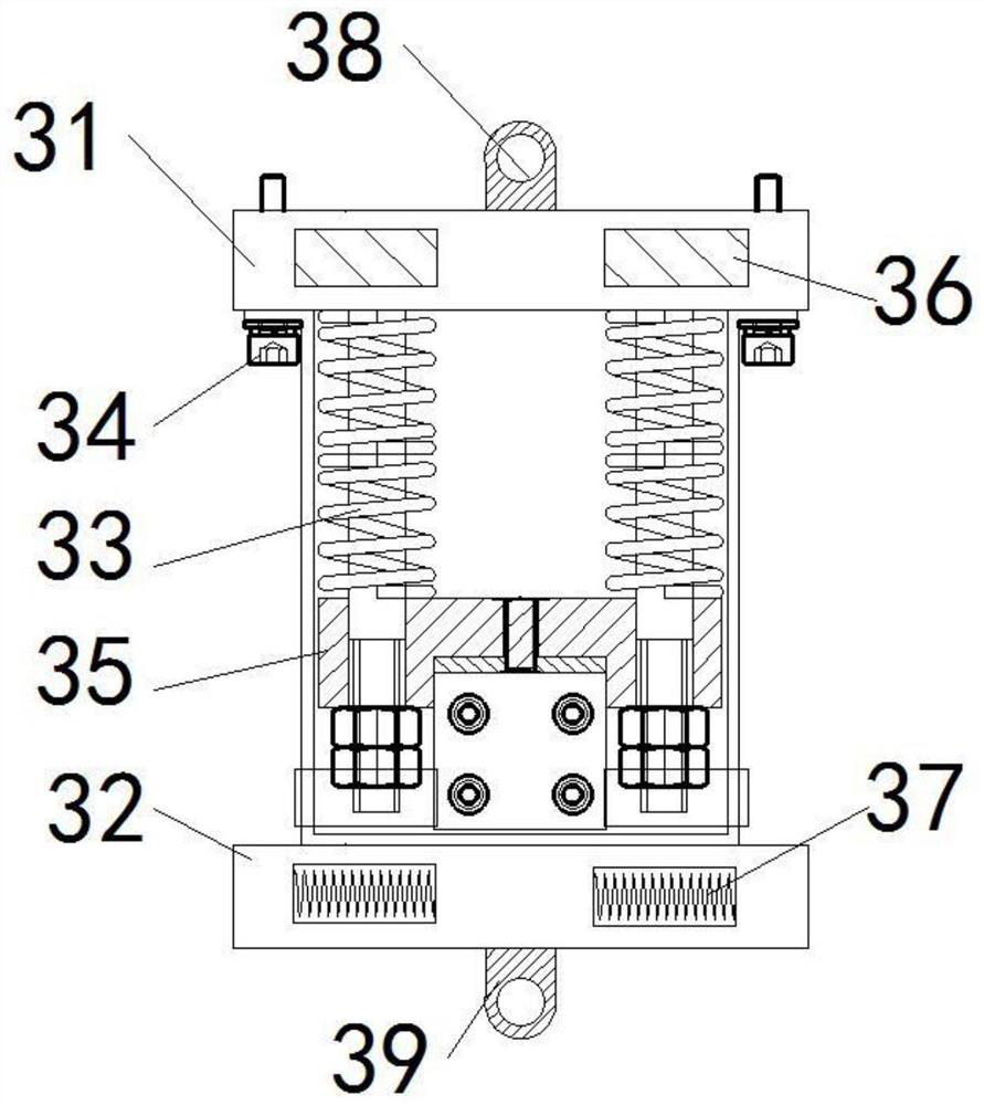
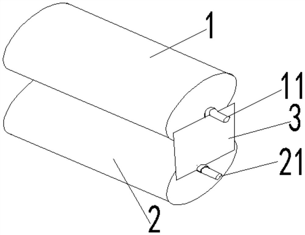
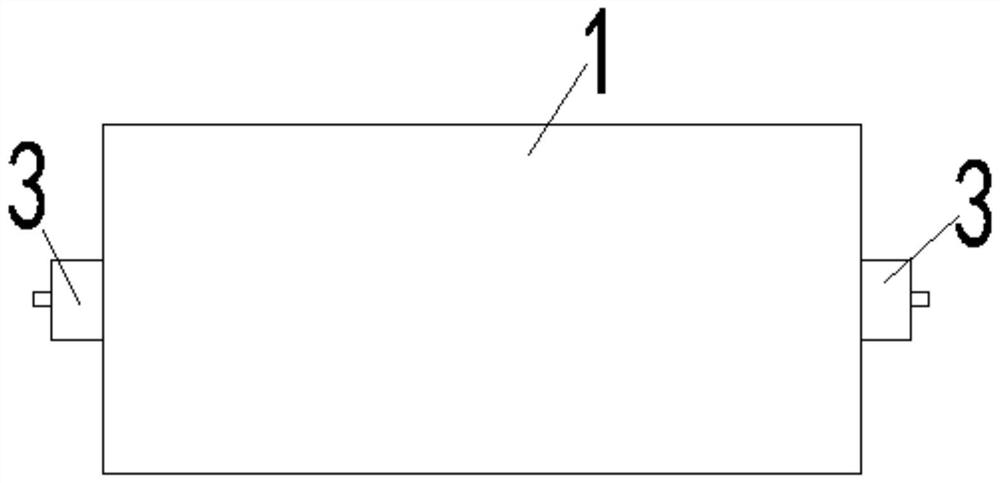
[0019] Such as figure 1 To Figure 4 As shown, a split offset printing press of the present invention includes a printing plate cylinder 1, a rubber cylinder 2, and an adjustment structure 3. The printing plate cylinder 1 includes a printing plate shaft 11, and the rubber cylinder 2 includes a rubber shaft 21, wherein the printing plate cylinder 1 and the rubber cylinder 2 Both sides of the rubber cylinder 2 are provided with adjustment structures 3, the upper and lower connection holes of the adjustment structure 3 ...


PUM


Abstract

The invention relates to the technical field of mechanical equipment, in particular to a split offset press. An adjusting structure comprises a plate cylinder connecting base, a blanket cylinder connecting base, springs, a sliding base and sliding column, magnetic conductive plates, electromagnets, a plate shaft connecting hole and a rubber shaft connecting hole, wherein the plate cylinder connecting base and the blanket cylinder connecting base are installed on the two sides of the sliding base and sliding column respectively, and the springs are arranged on two sliding columns of the sliding base and sliding column respectively. The upper portion of each spring is provided with the corresponding magnetic conductive plate, the lower portion of each spring is provided with the corresponding electromagnet, the two magnetic conductive plates are arranged in the plate cylinder connecting base, the two electromagnets are arranged in the blanket cylinder connecting base, the upper portion of the plate cylinder connecting base is provided with the printing plate shaft connecting hole, and the lower portion of the blanket cylinder connecting base is provided with the rubber shaft connecting hole. The printing plate shaft connecting hole is used for being connected with a printing plate shaft of a printing plate cylinder, and the rubber shaft connecting hole is used for being connected with a rubber shaft of a rubber cylinder. The springs, the sliding columns of the sliding base and sliding column, the magnetic conductive plates and the electromagnets on left side and right side are left-right symmetrical about the connecting line between the printing plate shaft connecting hole and the rubber shaft connecting hole. The device can be stably used for a long time.

Description

technical field [0001] The invention relates to the technical field of mechanical equipment, in particular to a folio offset printing machine. Background technique [0002] In general, the rubber cylinder and the plate cylinder in the offset printing machine are always in contact, which is suitable for printing on continuous paper. When printing on cut paper, it is best to separate the rubber cylinder from the plate cylinder. Make sure that the cut paper will not be mistaken. [0003] In this regard, the Chinese utility model patent "A Conjugate Cam Driving Mechanism for Two-Color Offset Press" (Application No. 201820982316.9) discloses a device for adjusting the mutual position of the rubber cylinder and the printing plate cylinder through a mechanism such as a connecting rod. The cylinder and the printing plate cylinder are relatively heavy, and the lever is too long. The pry bar in the driving mechanism is easily deformed, resulting in the intermittent increase of the ru...

Claims


Application Information

Patent Timeline
IPC IPC(8): B41F7/02B41F7/20B41F13/38
CPCB41F7/02B41F7/20B41F13/38
Inventor 刘泽胜姜平
Owner 荆州市今印印务有限公司
Why Eureka
Try Eureka