
An automatic bag sticking machine

A pocketing machine, automatic technology, applied in the direction of the cloth pressing mechanism, cloth feeding mechanism, sewing machine components, etc., can solve the problems of the unloading board hitting other equipment, mechanical damage, etc., and achieves the degree of automation and is easy to control and reduce Bearing capacity and the effect of reducing production costs

Active Publication Date: 2022-07-22
WENZHOU GUTAI MACHINERY TECH CO LTD
View PDF5 Cites 0 Cited by
  • Summary
  • Abstract
  • Description
  • Claims
  • Application Information

AI Technical Summary

Problems solved by technology

[0004] However, in the actual use process, the inventor found that the process of pasting the bag of the automatic bag pasting machine is automatically completed after the control system is programmed. to other equipment, resulting in mechanical damage

Method used


Image

  • An automatic bag sticking machine
  • An automatic bag sticking machine
  • An automatic bag sticking machine

Examples


Embodiment 1

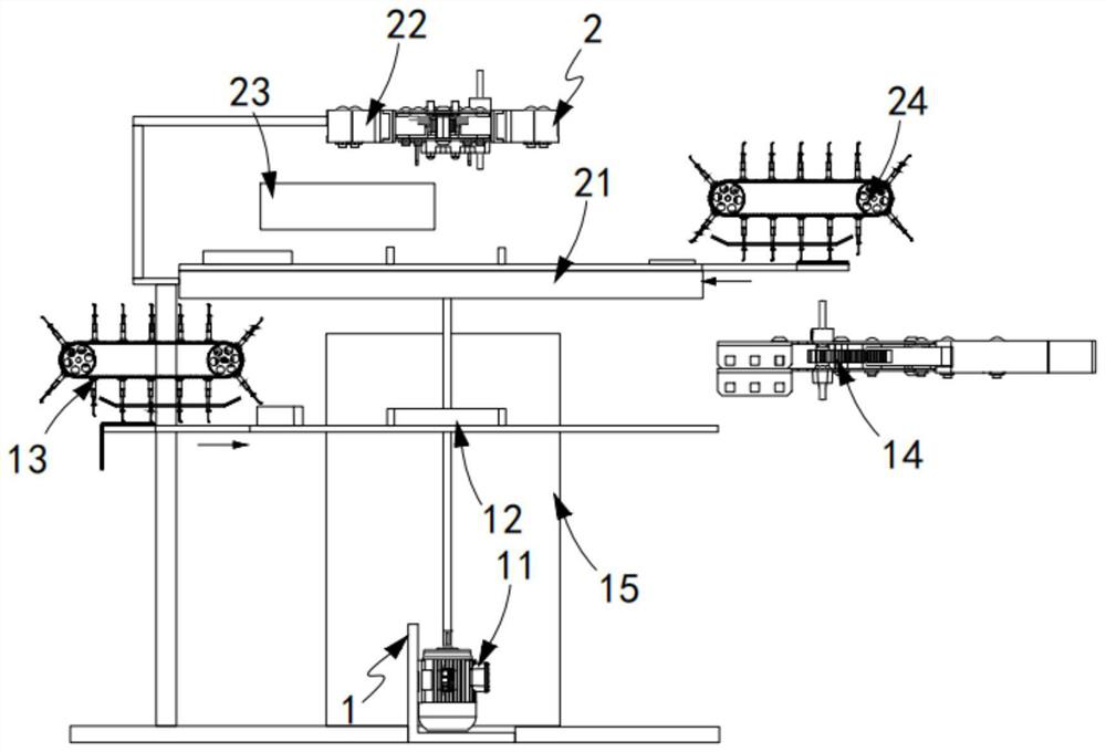
[0048] like figure 1 As shown, an automatic bag patching machine, comprising:

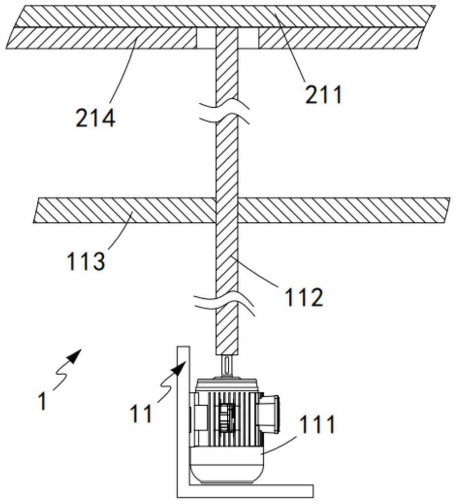
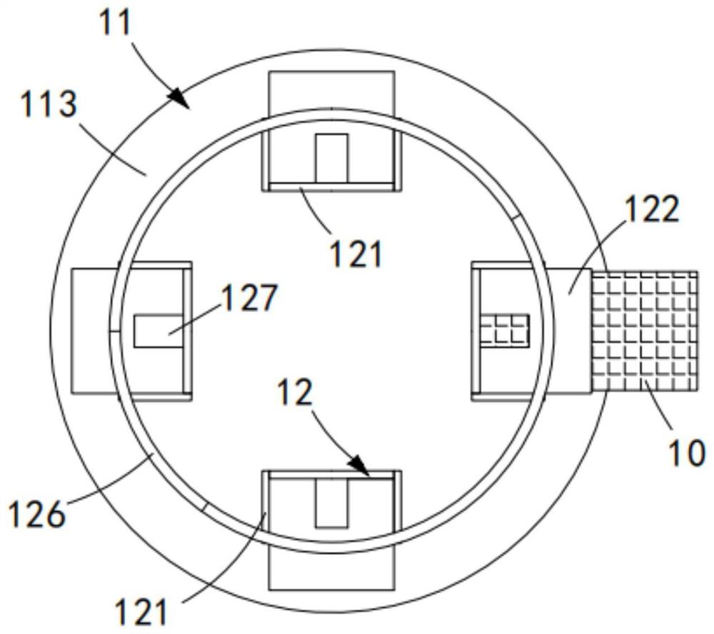
[0049] A station switching mechanism 1, the station switching mechanism 1 includes a drive assembly 11 and a first bearing that is arranged in several groups at equal intervals along the circumferential direction of the drive assembly 11 and performs intermittent circular rotation under the drive of the drive assembly 11 Assembly 12, the drive assembly 11 is sequentially provided with a feeding station 101, a bag receiving station 102, a bag sticking station 103 and an output station 104 along its circumferential direction;

[0050] The hemming mechanism 2 is arranged above the station switching mechanism 1 , and the hemming mechanism 2 includes a second bearing assembly 21 and a hemming assembly 22 arranged on the second bearing assembly 21 and a transfer assembly 23 arranged on the second carrying assembly 21, the second carrying assembly 21 is sequentially provided with a hemming station 201, a...

Embodiment 2

[0098] like Figure 16 to Figure 17 As shown, the same or corresponding components as those in the first embodiment are given the corresponding reference numerals as in the first embodiment. For the sake of brevity, only the points of difference from the first embodiment are described below. The difference between the second embodiment and the first embodiment is:

[0099] further, as Figure 16 to Figure 17 As shown, the output assembly 15 includes a lead-out track 151 and a collection box 152 arranged below the output end of the lead-out track 151, and the lead-out track 151 and the trouser leg 10 hang down on the drive assembly 11 part of the fitting arrangement;

[0100] The lead-out rail 151 is located between the pocket placement station 103 and the output station 104 , and the distance from the lead-out rail 151 to the center of the drive assembly 11 increases.

[0101] In this embodiment, the work of automatically pulling out the rear trouser legs of the patch pocket...


PUM


Abstract

The invention relates to an automatic bag patching machine, comprising a station switching mechanism, which includes a driving component and a first bearing component; In the circumferential direction, a folding station, a suspended station, a blanking station and an upload station are arranged in sequence. The transfer component is set on the suspended station, and the upload station is provided with an upload component; The bag patching station is provided with a bag patching component, and the output station is provided with an output component; the uploading station is located just above the bag patching station; the invention solves the problem that the bag patching process of the automatic bag patching machine is controlled After the system is programmed, various operations are automatically completed. Since it is automatic, if the program is wrong, the feeding board will hit other equipment during the movement, resulting in technical problems of mechanical damage.

Description

technical field [0001] The invention relates to the technical field of bag patching machines, in particular to an automatic bag patching machine. Background technique [0002] Chain beading machine, also known as chain stitch sewing machine, uses one or more sewing threads to form one or more stitches on the sewing material, so that one or more layers of sewing material are interlaced or sewn together. Machine, in order to improve work efficiency, the chain beading machine will also be equipped with a thread breaker to automatically cut off the sewing thread. [0003] The patent document with the patent number of CN2017210069712 discloses a wire breaking device for a chain bead edger, comprising a cylinder with a piston rod and a cutting knife driven by the piston rod. The cylinder is provided with a casing at the end of the piston rod, and the casing is provided with There is a movable groove for the piston rod to move, and the outer casing is provided with a cutting block...

Claims


Application Information

Patent Timeline
Patent Type & Authority Patents(China)
IPC IPC(8): D05B35/06D05B35/08D05B29/00D05B29/02
CPCD05B35/06D05B35/08D05B29/00D05B29/02
Inventor 张江陈光福
Owner WENZHOU GUTAI MACHINERY TECH CO LTD
Learn More