Exhaust tube mounting construction method for building industrial fresh air system

A technology of fresh air system and construction method, applied in ventilation system, heating method, pipeline arrangement and other directions, can solve the problems of easy deviation, flush exhaust pipe, poor docking accuracy at the interface, etc., so as to improve the installation accuracy and improve the The effect of docking accuracy and improved sealing

Inactive Publication Date: 2021-08-27
方教勇
View PDF0 Cites 0 Cited by
  • Summary
  • Abstract
  • Description
  • Claims
  • Application Information

AI Technical Summary

Problems solved by technology

[0005] The present invention can solve the problem that the existing exhaust pipe installation construction device cannot stably clamp the exhaust pipe before the installation of the exhaust pipe, which causes the exhaust pipe to be unstable and easy to shift when it is lifted and installed, and affects the installation accuracy of the exhaust pipe. It can also solve the problem that the existing exhaust pipe installation and construction device cannot stably lift the exhaust pipe to be flush with the exhaust pipe to be installed, which causes the exhaust pipe to be easily tilted during butt installation, and the butt joint accuracy at the interface is poor , the interface is prone to air leakage

Method used


Image

  • Exhaust tube mounting construction method for building industrial fresh air system
  • Exhaust tube mounting construction method for building industrial fresh air system
  • Exhaust tube mounting construction method for building industrial fresh air system

Examples


Embodiment Construction

[0034] The embodiments of the present invention will be described in detail below with reference to the accompanying drawings, but the present invention can be implemented in many different ways defined and covered by the claims.

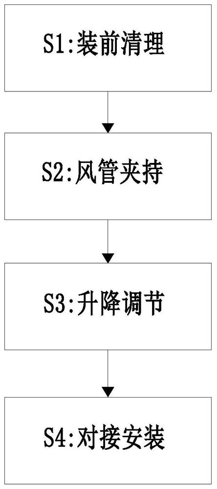
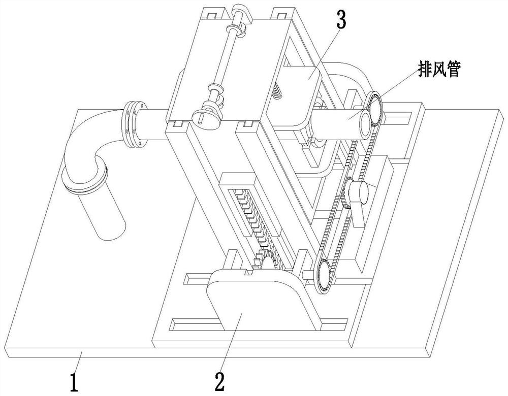
[0035] Such as Figure 1 to Figure 7 As shown, a method for installing an exhaust pipe for an industrial fresh air system uses an installation and construction device for an exhaust pipe for an industrial fresh air system. The installation and construction device for an exhaust pipe for an industrial fresh air system includes a base plate 1 and a lifting and docking mechanism 2 and a clamping mechanism 3, the lifting and docking mechanism 2 is installed on the base plate 1, and the clamping mechanism 3 is installed on the lifting and docking mechanism 2 by sliding fit.

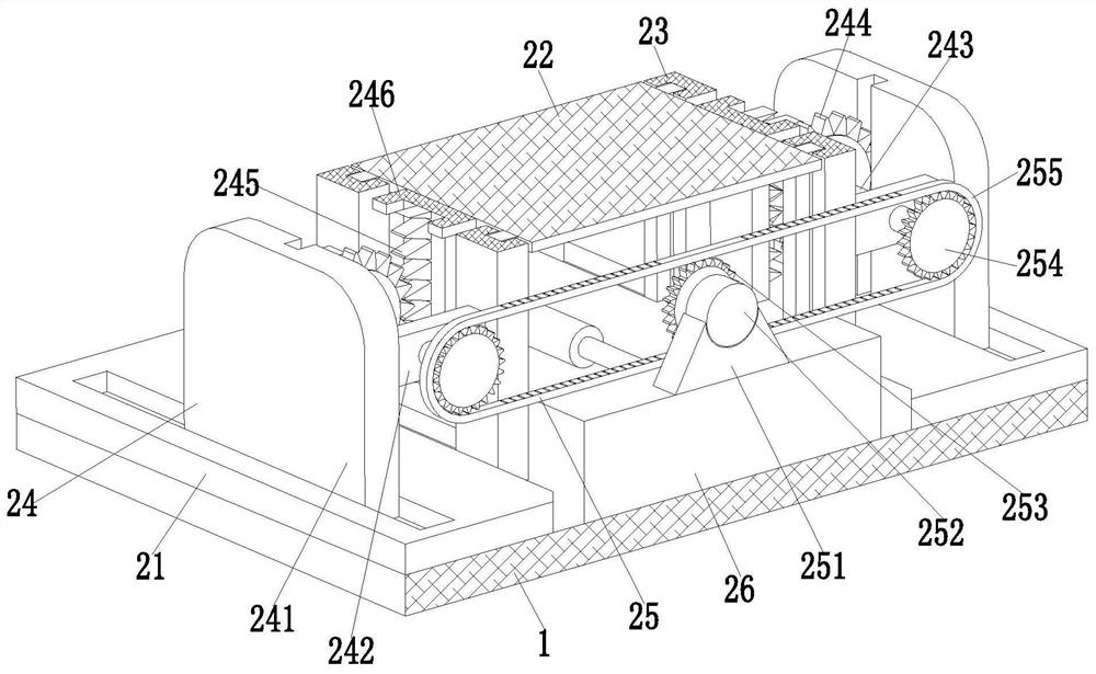
[0036]The lifting docking mechanism 2 includes a support plate 21, a docking frame 22, a limit bar 23, a lifting branch chain 24, a sprocket branch chain 25, a sliding seat 26, a do...


PUM


Abstract

The invention relates to an exhaust tube mounting construction method for building an industrial fresh air system, an exhaust tube mounting construction device for building the industrial fresh air system is used. The exhaust tube mounting construction device for building the industrial fresh air system comprises a bottom plate, a lifting butt joint mechanism and a clamping mechanism, wherein the lifting butt joint mechanism is mounted on the bottom plate; and a clamping mechanism is mounted on the lifting butt joint mechanism in a sliding fit mode. The exhaust tube mounting construction device can solve the problems that an existing exhaust tube mounting construction device cannot stably clamp an exhaust tube before the exhaust tube is installed, so that the exhaust tube is unstable and prone to deviation during lifting mounting, and the mounting precision of the exhaust tube is affected, and further can solve the problems that an existing exhaust tube mounting construction device cannot stably lift the exhaust tube to be flush with the exhaust tube to be subjected to butt joint mounting, so that the exhaust tube is prone to inclination during butt joint mounting, the butt joint precision of the connector is poor, and air leakage is prone to occurring to the connector.

Description

technical field [0001] The invention relates to the technical field of exhaust pipe installation, in particular to a method for installing an exhaust pipe in an industrial fresh air system. Background technique [0002] The fresh air system is an independent air treatment system composed of an air supply system and an exhaust system. It is divided into two types: ducted fresh air system and ductless fresh air system. The ducted fresh air system is composed of fresh air fans and pipe fittings. The outdoor air is purified by the fresh air fans and introduced into the room, and the indoor air is discharged through the pipes. The ductless fresh air system is composed of fresh air fans. Relatively speaking, the ducted fresh air system is more suitable for industrial or large-area office areas due to the large amount of engineering, while the ductless fresh air system is more suitable for home use because of its easy installation. The exhaust pipe is to prevent the harmful substa...

Claims


Application Information

Patent Timeline
Patent Type & Authority Applications(China)
IPC IPC(8): F24F13/02F24F7/06
CPCF24F7/06F24F13/0254F24F13/0272
Inventor 方教勇
Owner 方教勇
Why Eureka
Try Eureka