Intelligent vehicle-mounted monitoring system with intelligent power supply control circuit
A vehicle-mounted monitoring system and intelligent power control technology, applied in control/regulation systems, circuit monitoring/indication, closed-circuit television systems, etc., can solve problems such as high temperature of the imaging chip, slow response of the control system, and low power consumption of the imaging chip. Achieve the effect of large capacity, strong versatility and high efficiency
- Summary
- Abstract
- Description
- Claims
- Application Information
AI Technical Summary
Problems solved by technology
Method used
Image

Examples
Embodiment 1
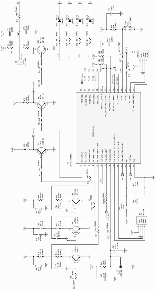
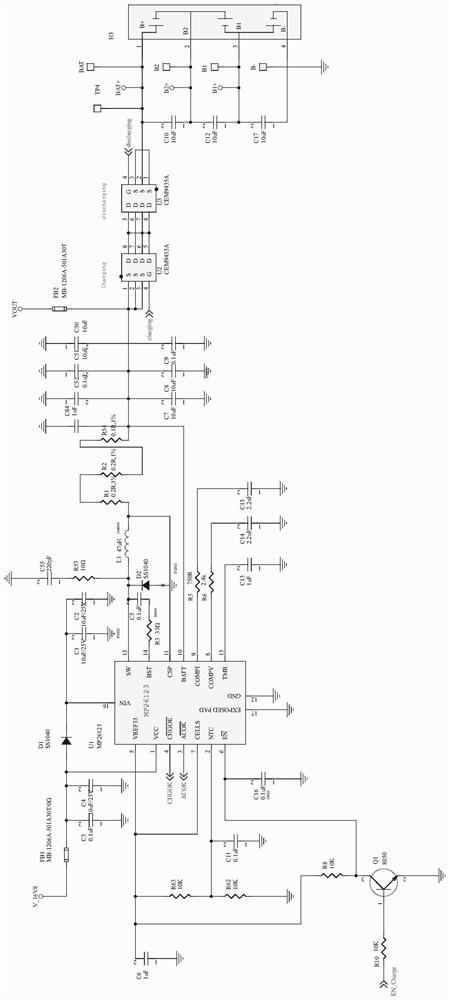
[0037] Example 1, such as Figure 1-5 As shown, an intelligent vehicle monitoring system with an intelligent power supply control circuit includes: a power conversion module, a charging module, a main control board power module, a main control module and a protection module, and the power conversion module provides a stable 16.8V voltage , the charging module is used to manage the charging and discharging of the battery pack H5, the power input terminal of the charging module is connected to the power conversion module, the power output terminal is connected to a load, the charging module is connected to the main control module, the The main control board power module provides a stable 3.3V voltage for the main control module, the power input terminal of the main control board power module is connected to the power conversion module and the charging module, and the main control module includes a main control chip U8, leakage protection circuit, temperature protection circuit a...
Embodiment 2
[0038] Example 2, such as Figure 5 As shown, the protection module includes a connector H7 and a triode Q3. The first lead of pin 1 of the connector H7 is grounded through the TVS diode D15, the second lead is connected to the load, and the 2 transistors of the connector H7 The first lead of pin is grounded through resistors R25 and R28, the second lead is connected to the first end of resistor R21, the second end of said resistor R21 is connected to pin 7 of said main control chip U8, and the emitter of said triode Q3 Grounded, the first lead of the collector of the triode Q3 is connected to the 3.3V power supply through the resistor R17, the second lead is connected to the 17 pin of the main control chip U8, and the first lead of the base of the triode Q3 is connected to the resistor R59 Grounded, the second lead is grounded through diode D16 and capacitor C79, the third lead is connected to the first end of resistor R21 through resistor R51, wherein capacitors C27, C78, ...
Embodiment 3
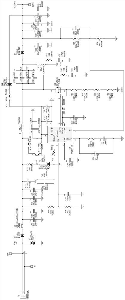
[0039] Example 3, such as figure 2As shown, the power conversion module includes a connector H6 and a chip U5, the 2-pin of the connector H6 is grounded, the first lead of the 1-pin of the connector H6 is grounded through the TVS diode D7, and the second lead is connected to the ground. The anode of the diode D5, the cathode of the diode D5 is connected to the first end of the magnetic bead FB6, the first lead of the second end of the magnetic bead FB6 is grounded through the resistors R19 and R24, and the second lead is connected to the first end of the resistor R15, The first lead of the second end of the resistor R15 is grounded through the diode D8, the second lead is connected to the base of the transistor Q2, the collector of the transistor Q2 is connected to the first end of the resistor R16, and the second end of the resistor R16 is connected to The first end of the resistor R15, the emitter of the triode Q2 is connected to the 8-pin of the chip U5 through the resisto...
PUM
 Abstract
Description
Claims
Application Information
 - R&D
- Intellectual Property
- Life Sciences
- Materials
- Tech Scout
- Unparalleled Data Quality
- Higher Quality Content
- 60% Fewer Hallucinations
Browse by: Latest US Patents, China's latest patents, Technical Efficacy Thesaurus, Application Domain, Technology Topic, Popular Technical Reports.
© 2025 PatSnap. All rights reserved.Legal|Privacy policy|Modern Slavery Act Transparency Statement|Sitemap|About US| Contact US: help@patsnap.com