Mounting method of modularized steel structure

An installation method and steel structure technology, applied to the preparation of building components on site, the connectors of formwork/formwork/work frame, building components, etc., can solve the difficulty of construction, uncontrollable risks, and the difficulty of protecting the finished products of the underlying equipment Major problems, to achieve the effect of reducing installation safety risks, reducing installation safety risks, and reducing on-site installation and calibration risks

Active Publication Date: 2021-08-31
CHINA HAISUM ENG
View PDF5 Cites 2 Cited by
  • Summary
  • Abstract
  • Description
  • Claims
  • Application Information

AI Technical Summary

Problems solved by technology

But there are also unfavorable situations, for example: the 24-meter-long column is divided into two parts, and the on-site assembly and welding require the precision to be within 3mm, which makes the construction difficult and the risks uncontrollable; it is difficult to protect the finished products of the underlying equipment

Method used


Image

  • Mounting method of modularized steel structure
  • Mounting method of modularized steel structure
  • Mounting method of modularized steel structure

Examples


Embodiment

[0038] A method for installing a modular steel structure specifically includes the following steps:

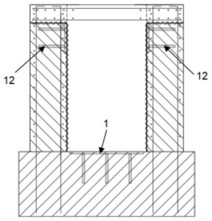
[0039] Step 1: Bind ground beam reinforcement and formwork on the foundation to obtain a plurality of foundation units.

[0040] Among them, the ground beam reinforcement includes multiple vertically interlaced steel bars. After being bundled, multiple horizontal steel cages parallel to each other and multiple vertical steel cages parallel to each other are obtained. .

[0041] Step 2. At the intersection of the foundation cells, bind the cup-mouth steel bars upward along the foundation and set up the formwork to obtain the cup-mouth reinforcement cage base and cup-mouth reinforcement cage connected together. The upper end of the cup-mouth reinforcement base and the ground beam reinforcement The upper surface of the ground beam is flush with the upper surface of the column foot and the cup mouth reinforcement cage extends upwards along the upper surface of the ground beam rei...


PUM


Abstract

The invention relates to a mounting method of a modularized steel structure. The mounting method comprises the following steps of binding ground beam reinforcing steel bars and supporting formworks on a foundation to obtain a plurality of foundation cells; upwards binding cup rabbet reinforcing steel bars at the intersections of the foundation cells and erecting a formwork to obtain a cup rabbet reinforcing steel bar cage base and a cup rabbet reinforcing steel bar cage, arranging a column foot positioning bottom plate and a column foot side wall mounting plate, and then erecting the formwork; after the elevation of the column foot positioning bottom plate is rechecked, pouring concrete into a ground beam steel bar cup opening steel reinforcement cage base, and completing construction of a ground beam and a cup opening base; finishing floor construction; placing a steel structure column in the cup opening; mounting bottom-layer connecting beams between the steel structure columns to form a first-layer frame, and mounting the cross beams layer by layer to form a multi-layer frame structure. According to the method, simultaneous construction of the cup opening column foot and the floor can be achieved, the steel structure column does not need to be divided, the stability of the steel structure column in the installation process is improved in a cup opening mode, the installation safety risk is reduced, and the finished product protection difficulty is greatly reduced.

Description

technical field [0001] The invention relates to a modular steel structure, in particular to a method for installing the modular steel structure. Background technique [0002] In some factory expansion projects, the main production device needs to adopt multi-layer steel structure devices, and the underlying equipment needs to be installed in advance. However, the on-site installation space is limited and the construction period is short, which brings a lot of inconvenience to the construction. According to the requirements of the steel structure code, the multi-layer steel structure device needs to adopt the form of embedded column feet. If the traditional construction method is adopted, the following two methods can be used: [0003] 1. After the pile foundation construction is completed, the device area will be excavated as a whole, and then the foundation construction will be carried out. After the foundation strength is reached, the steel structure column will be install...

Claims


Application Information

Patent Timeline
Patent Type & Authority Applications(China)
IPC IPC(8): E04G13/04E04G17/00E04B1/00E04B1/16E04B1/24E04B1/58
CPCE04G13/04E04G17/002E04B1/0007E04B1/165E04B1/2403E04B1/24E04B2001/2463
Inventor 田克胜陈建华姚志磊
Owner CHINA HAISUM ENG
Why Eureka
Try Eureka