
Drill rod straightness detection device and method

A detection device and straightness technology, applied in measurement devices, instruments, etc., can solve the problems of inaccurate data, difficult establishment of detection benchmarks, and lack of effective detection methods and devices, so as to ensure detection accuracy and strong engineering achievability. , The effect of efficient straightness detection

Active Publication Date: 2021-08-31
JIANGSU XCMG CONSTR MASCH RES INST LTD
View PDF12 Cites 1 Cited by
  • Summary
  • Abstract
  • Description
  • Claims
  • Application Information

AI Technical Summary

Problems solved by technology

Since the key bars are evenly distributed on the outer cylindrical surface of the drill pipe after the key bars are welded, it is difficult to establish a detection benchmark and the data is inaccurate. There is no effective detection method and device.

Method used


Image

  • Drill rod straightness detection device and method
  • Drill rod straightness detection device and method
  • Drill rod straightness detection device and method

Examples


Embodiment 1

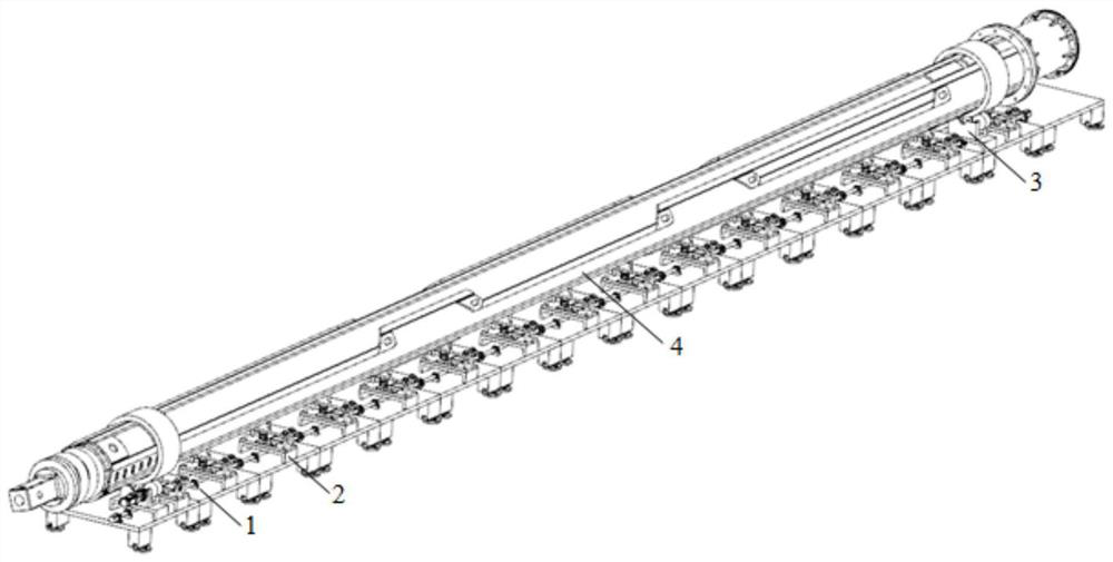
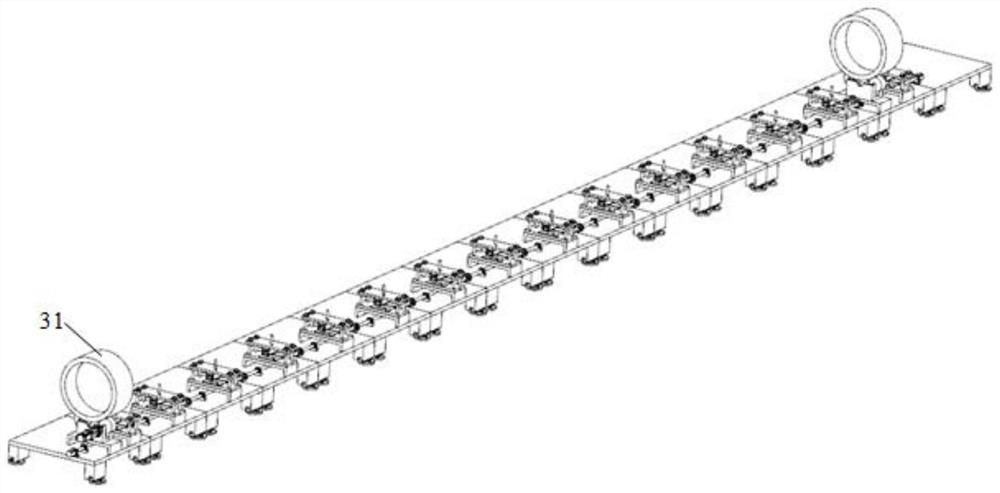
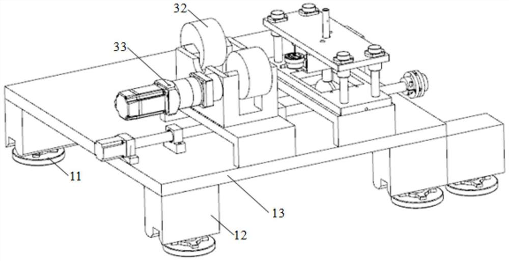
[0048] An embodiment of the present invention provides a drill pipe straightness detection device, such as Figure 1-7 As shown, it includes a first support mechanism 1, a second support mechanism 3 and a detection mechanism 2;

[0049] The second support mechanism 3 is connected to the first support mechanism 1, supported by the first support mechanism 1, and used to support the drill pipe 4 to be tested;

[0050] The detection mechanism 2 includes a drive unit and a spatial position information acquisition unit; the drive unit drives the spatial position information acquisition unit to rotate; the spatial position information acquisition unit is used to contact the drill pipe 4 to be measured, and collect the measured position in real time. Spatial position information of the drill pipe 4.

[0051] In a specific implementation manner of the embodiment of the present invention, such as Figure 4-5 As shown, the drive unit includes a drive motor 21, a connecting rod 22, a su...

Embodiment 2

[0080] A method for detecting the straightness of a drill pipe is provided in an embodiment of the present invention, comprising the following steps:

[0081] Utilizing the first supporting mechanism to support the second supporting mechanism, while using the second supporting mechanism to support the drill pipe to be tested;

[0082] Utilize the drive unit to drive the rotation of the spatial position information collection unit, and when the spatial position information collection unit turns to correspond to the non-line position of the drill pipe to be measured, control the spatial position information collection unit and the outer wall of the drill pipe to be measured Contact to collect the spatial position information of the drill pipe to be tested. .

[0083] The method in the embodiment of the present invention can be realized based on the straightness detection device of the drill pipe 4 in the first embodiment.


PUM


Abstract

The invention discloses a drill rod straightness detection device and method. The device comprises a first supporting mechanism, a second supporting mechanism and a detection mechanism; wherein the second supporting mechanism is connected with the first supporting mechanism, is supported by the first supporting mechanism and is used for supporting a drill rod to be tested; the detection mechanism comprises a driving unit and a spatial position information acquisition unit; the driving unit drives the spatial position information acquisition unit to rotate; the spatial position information acquisition unit is used for being in contact with a to-be-detected drill rod and acquiring spatial position information of the to-be-detected drill rod in real time. According to the invention, the straightness of the drill rod with the key bar can be conveniently, accurately and quickly detected in the production process, so that the device and method has important significance for improving the processing quality and the process of the drill rod.

Description

technical field [0001] The invention belongs to the field of straightness detection, and in particular relates to a device and method for straightness detection of drill pipes. Background technique [0002] The drill pipe is the core component of the rotary drilling rig, which transmits the torque of the power head to the drill tool and the guide drill tool for drilling. Its straightness directly affects the hole quality of the rotary drilling rig. The out-of-tolerance straightness of the drill pipe will also cause sticking, wear and early failure of the drill pipe and the power head, which directly affects the performance and life of the rotary drilling rig. In drill pipe manufacturing, the straightness of the three processes of steel pipe entering the factory, steel pipe tailor welding, and key bar welding determines the straightness of the drill pipe, and straightness detection and control are required, especially after key bar welding. Since the key strips are evenly d...

Claims


Application Information

Patent Timeline
Patent Type & Authority Applications(China)
IPC IPC(8): G01B21/24
CPCG01B21/24
Inventor 陈新春蹤雪梅何冰
Owner JIANGSU XCMG CONSTR MASCH RES INST LTD
Learn More