
Handle controller led lamp positioning method and system based on computer vision

A computer vision, led light technology, applied in computer parts, computing, instruments and other directions, can solve the problems of poor positioning accuracy, poor anti-occlusion, sensitive to light conditions, etc., to achieve low cost, spatial positioning, stability and durability high effect

Pending Publication Date: 2021-08-31
南京奇元科技有限公司
View PDF0 Cites 0 Cited by
  • Summary
  • Abstract
  • Description
  • Claims
  • Application Information

AI Technical Summary

Problems solved by technology

The disadvantages are that the positioning accuracy is relatively poor, the anti-occlusion performance is poor, and it is sensitive to the surrounding lighting conditions.
[0007] To sum up, the existing technology has application defects to varying degrees in terms of stability, durability, cost, etc., and there is currently a lack of a positioning technology that can take into account the above problems

Method used


Image

  • Handle controller led lamp positioning method and system based on computer vision
  • Handle controller led lamp positioning method and system based on computer vision
  • Handle controller led lamp positioning method and system based on computer vision

Examples


Embodiment 1

[0060] The embodiments of the present invention focus on solving the problem of positioning the LED lights on the handle controller. In the VR space positioning interactive system, by using the external camera to capture the two-dimensional image corresponding to the handle controller, using the computer vision method to locate the coordinates of the LED light on the handle controller in the two-dimensional image, and then carry out three-dimensional modeling of the LED light, Realize the real-time tracking of the handle controller, so as to complete the spatial positioning interaction of VR. The handle controller involved in the embodiment of the present invention has no less than 5 LED lights, and is an infrared handle.

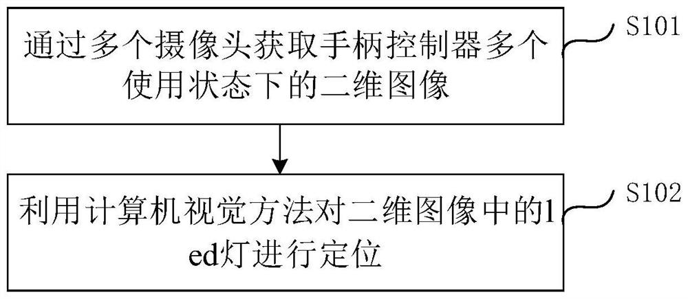
[0061] Please refer to figure 1 , the present embodiment proposes a computer vision-based method for positioning an LED light of a handle controller, including:

[0062] Step S101, acquiring two-dimensional images of the handle controller in multiple usag...

Embodiment 2

[0100] refer to Figure 7 , a computer vision-based handle controller led light positioning system, including:

[0101] An acquisition unit 10, configured to acquire two-dimensional images of the handle controller in multiple usage states through multiple cameras;

[0102] The positioning calculation unit 20 is configured to use a computer vision method to locate the LED lights in the two-dimensional image.

[0103]It can be understood that the above-mentioned computer vision-based handle controller LED light positioning system corresponds to the computer vision-based handle controller LED light positioning method in Embodiment 1. Any optional items in Embodiment 1 are also applicable to this embodiment, and will not be described in detail here.


PUM


Abstract

The embodiment of the invention discloses a handle controller led lamp positioning method and a system based on computer vision. The method comprises the steps that obtaining two-dimensional images of a handle controller in multiple use states through multiple cameras; and positioning the led lamp in the two-dimensional image by using a computer vision method. Compared with the prior art, the technical scheme of the invention combines an infrared optical positioning technology and a visible light positioning technology, utilizes a computer vision method to position and track an infrared handle with an LED lamp in a space so as to realize a space positioning interaction function of VR equipment, can track a handle controller in real time, and has the advantages of high stability and durability, and low cost..

Description

technical field [0001] The present invention relates to the technical field of VR space positioning and interaction, in particular to a computer vision-based method and system for positioning an LED light of a handle controller. Background technique [0002] With the development of technology, VR devices are gradually applied to people's lives. Consumers can wear VR head-mounted display devices and hold handle controllers to realize VR spatial positioning interaction and obtain a good interactive experience. [0003] However, there are mainly three common positioning methods at present: [0004] One is laser positioning. Laser positioning technology is to install several devices that can emit lasers in the space, and emit lasers that scan the space in both horizontal and vertical directions. Multiple laser induction receivers are placed on the positioned object, and the two beams of light reach the positioning object by calculating The angle difference of , so as to obtain...

Claims


Application Information

Patent Timeline
Patent Type & Authority Applications(China)
IPC IPC(8): G06T7/00G06T7/136G06T7/80G06K9/46G06K9/62
CPCG06T7/0002G06T7/136G06T7/80G06T2207/10004G06T2207/20016G06T2207/20021G06V10/44G06F18/2411
Inventor 程会云王西颖史明
Owner 南京奇元科技有限公司
Learn More