
Standing wave accelerating tube and accelerating device

An accelerator tube and standing wave technology, applied in linear accelerators, X-ray/γ-ray/particle irradiation therapy, radiotherapy, etc., can solve the problem of inability to switch keV-level rays and MeV-level rays.

Inactive Publication Date: 2021-08-31
CHINA INSTITUTE OF ATOMIC ENERGY
View PDF12 Cites 0 Cited by
  • Summary
  • Abstract
  • Description
  • Claims
  • Application Information

AI Technical Summary

Problems solved by technology

[0003] In view of this, the embodiment of the present application expects to provide a standing wave accelerating tube and an accelerating device to solve the problem in the prior art that keV-level rays and MeV-level rays cannot be switched

Method used


Image

  • Standing wave accelerating tube and accelerating device
  • Standing wave accelerating tube and accelerating device
  • Standing wave accelerating tube and accelerating device

Examples


Embodiment Construction

[0027] It should be noted that, in the case of no conflict, the embodiments in the present application and the technical features in the embodiments can be combined with each other, and the detailed description in the specific embodiment should be understood as an explanation of the present application, and should not be regarded as an explanation of the present application. Undue Restriction of Application.

[0028] In the description of the embodiments of this application, the orientations or positional relationships of "upper", "lower", "left", "right", "front", "back" are based on the attached figure 2 It should be understood that these orientation terms are only for the convenience of describing the application and simplifying the description, rather than indicating or implying that the referred device or element must have a specific orientation, be configured in a specific orientation, and operation and therefore should not be construed as limiting the application.

[...


PUM


Abstract

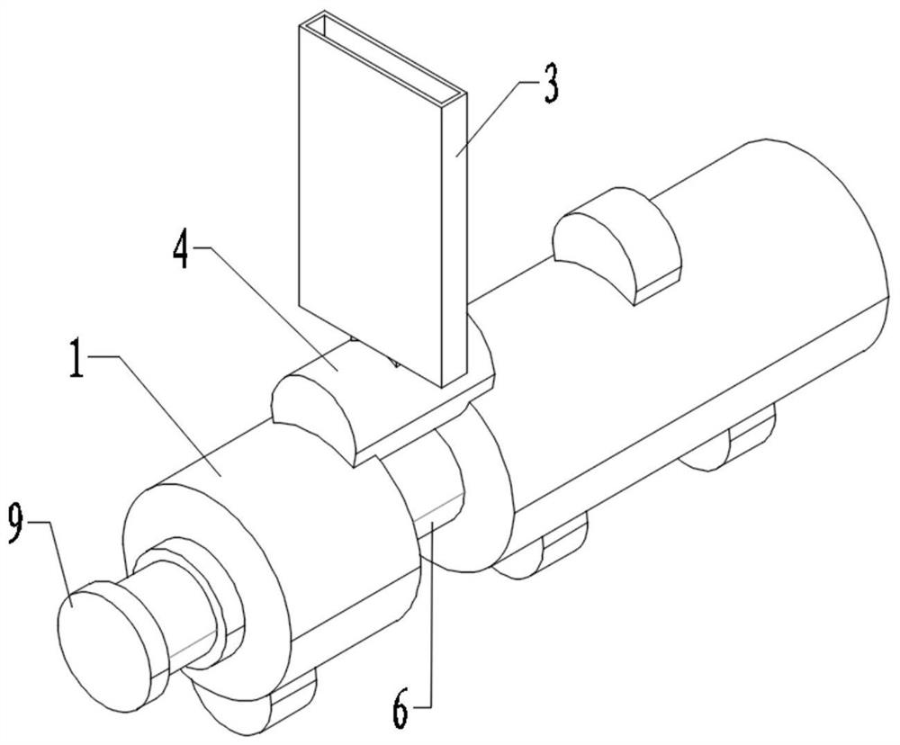
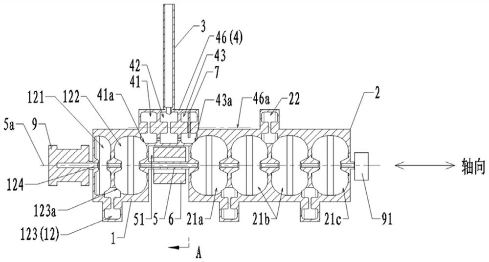
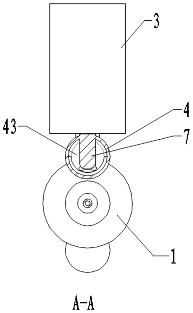
The embodiment of the invention discloses a standing wave accelerating tube and an accelerating device. The standing wave accelerating tube comprises a first body with a beam bunching structure, a second body, a waveguide, a bridge type coupler, an energy switch, a beam tube and a first focusing coil, wherein the second body is provided with a plurality of first side coupling cavities and a plurality of acceleration cavities distributed in the axial direction, and one first side coupling cavity is coupled with two adjacent acceleration cavities; the bridge type coupler is configured to distribute the radio frequency power fed by the waveguide into the beam bunching structure and the accelerating cavity; the energy switch is arranged on the bridge type coupler and can weaken or disappear the acceleration effect of the acceleration cavity; two ends of the beam tube are respectively communicated with the accelerating cavity at the first position and the beam bunching structure; and the first focusing coil is arranged on the beam tube. The standing wave accelerating tube and the accelerating device provided by the embodiment of the invention have the advantages that the keV-level particle beam and the MeV-level particle beam can be output, the low-energy ray dosage rate is improved, and the space occupation volume is reduced.

Description

technical field [0001] The present application relates to the technical field of accelerators, in particular to a standing wave accelerating tube and an accelerating device. Background technique [0002] In the prior art, electron linear accelerators can be divided into traveling wave accelerating tubes and standing wave accelerating tubes. The acceleration efficiency of standing wave accelerating tubes is generally higher than that of traveling wave accelerating tubes. The medical electron linear accelerator is currently the main equipment for radiotherapy, and the acceleration tube is the core component. Usually, the standing wave accelerator tube is used to accelerate the electrons to the required energy, and then output the radiation for treatment. During clinical treatment, the patient needs to be positioned first to verify the treatment plan. Generally, keV-level rays are used for imaging first, and then MeV-level rays are used for treatment. At present, most medical ...

Claims


Application Information

Patent Timeline
IPC IPC(8): H05H9/04H05H7/22A61N5/10
CPCH05H9/04H05H7/22A61N5/1077
Inventor 杨誉杨京鹤崔爱军朱志斌
Owner CHINA INSTITUTE OF ATOMIC ENERGY
Learn More