Centralized control device and centralized control system
A technology for centralized control and controlled equipment, which is applied in general control systems, control/regulation systems, computer control, etc., and can solve problems such as long recovery times
- Summary
- Abstract
- Description
- Claims
- Application Information
AI Technical Summary
Problems solved by technology
Method used
Image

Examples
no. 1 approach
[0032] The system controller, which is a centralized control device, performs centralized operations on various medical devices arranged in an operating room, for example, and can also control distribution of functions to scope switches of an endoscope. In this embodiment, when an error occurs, the function assigned to the scope switch is automatically changed, and when recovering from the error, the function assigned to the scope switch is automatically restored. As a result, the mirror switch can be effectively used even when an error occurs, and by allocating a function required for recovery from the error to the mirror switch, recovery from the error can be quickly performed.
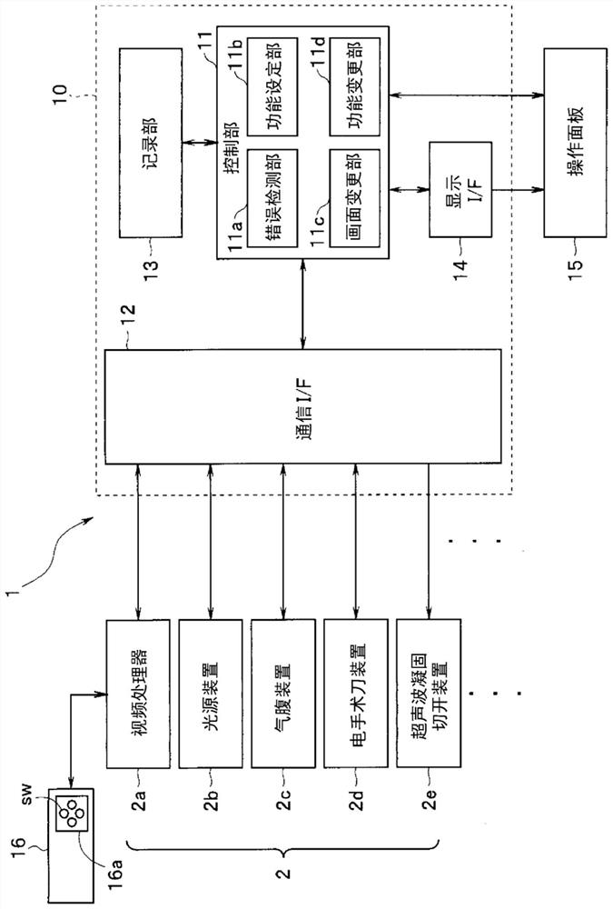
[0033] figure 1 It is a block diagram showing the centralized control system using the centralized control device of this invention.
[0034] Such as figure 1 As shown, the centralized control system 1 of the present embodiment includes a controlled device 2 composed of a plurality of medical devi...
no. 2 approach
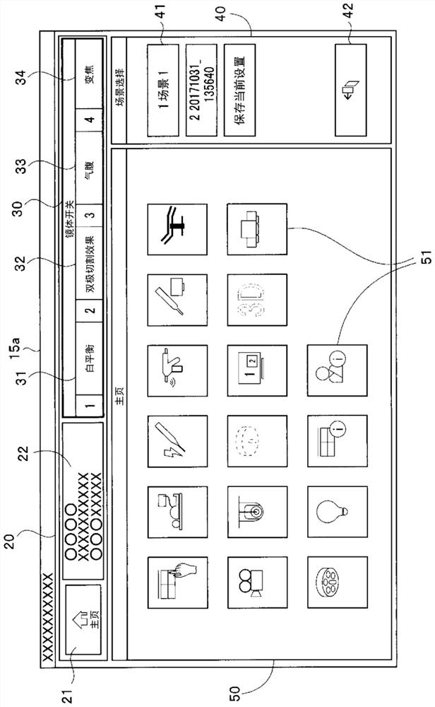
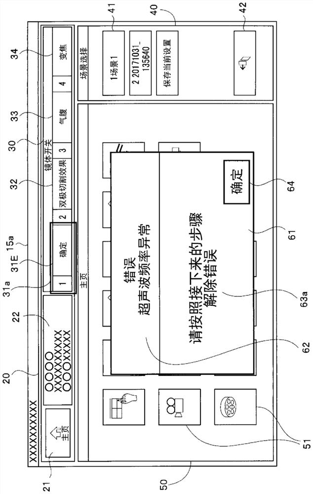
[0071] Figure 6 to Figure 10 Regarding the second embodiment of the present invention, Image 6 It is an explanatory diagram showing an example of the appearance of the mirror body switch, Figure 7 It is an explanatory diagram showing an example of a home screen. Figure 8 is an explanatory diagram showing an example of a setting screen for performing various settings on the controlled device 2, Figure 9 It is an explanatory diagram showing an example of the home screen when an error occurs, Figure 10 It is an explanatory diagram showing an example of a batch setting screen when an error occurs. The hardware structure of this embodiment and figure 1 Same, description omitted. This embodiment shows the operation display and the allocation function of the scope switch sw differently from the first embodiment, and it is possible to perform collective setting for easy recovery from errors.
[0072] Image 6 An example of the scope switch group 16a provided on the operat...
no. 3 approach
[0095] Figure 13 with Figure 14 Regarding the third embodiment of the present invention, Figure 13 is an explanatory diagram showing an example of a setting screen for performing various settings on the controlled device 2, Figure 14 It is an explanatory diagram showing an example of a home screen when an error occurs. The hardware structure of this embodiment and figure 1 Same, description omitted. This embodiment shows the assignment of the operation display and the scope switch sw differently from the first embodiment, and makes it easy to perform white balance adjustment when the white balance is not adjusted.
[0096] (in normal state)
[0097] Figure 13 show with Figure 8 The same setting screen. exist Figure 13 In the example of , the setting display 53 includes the setting of white balance adjustment, the setting of the light quantity of the light source, the setting based on A setting, the setting of the output value of the electric scalpel, and the se...
PUM
 Abstract
Description
Claims
Application Information
 - R&D
- Intellectual Property
- Life Sciences
- Materials
- Tech Scout
- Unparalleled Data Quality
- Higher Quality Content
- 60% Fewer Hallucinations
Browse by: Latest US Patents, China's latest patents, Technical Efficacy Thesaurus, Application Domain, Technology Topic, Popular Technical Reports.
© 2025 PatSnap. All rights reserved.Legal|Privacy policy|Modern Slavery Act Transparency Statement|Sitemap|About US| Contact US: help@patsnap.com