Adjustable assembly line table bed and using method
An assembly line and adjustable technology, applied in conveyors, mechanical conveyors, transportation and packaging, etc., can solve the problems of increasing the workload of staff, inconvenience of staff, and more time, saving the number of production workers, specialization The effect of high degree of production cost saving
- Summary
- Abstract
- Description
- Claims
- Application Information
AI Technical Summary
Problems solved by technology
Method used
Image
Examples
Embodiment 1
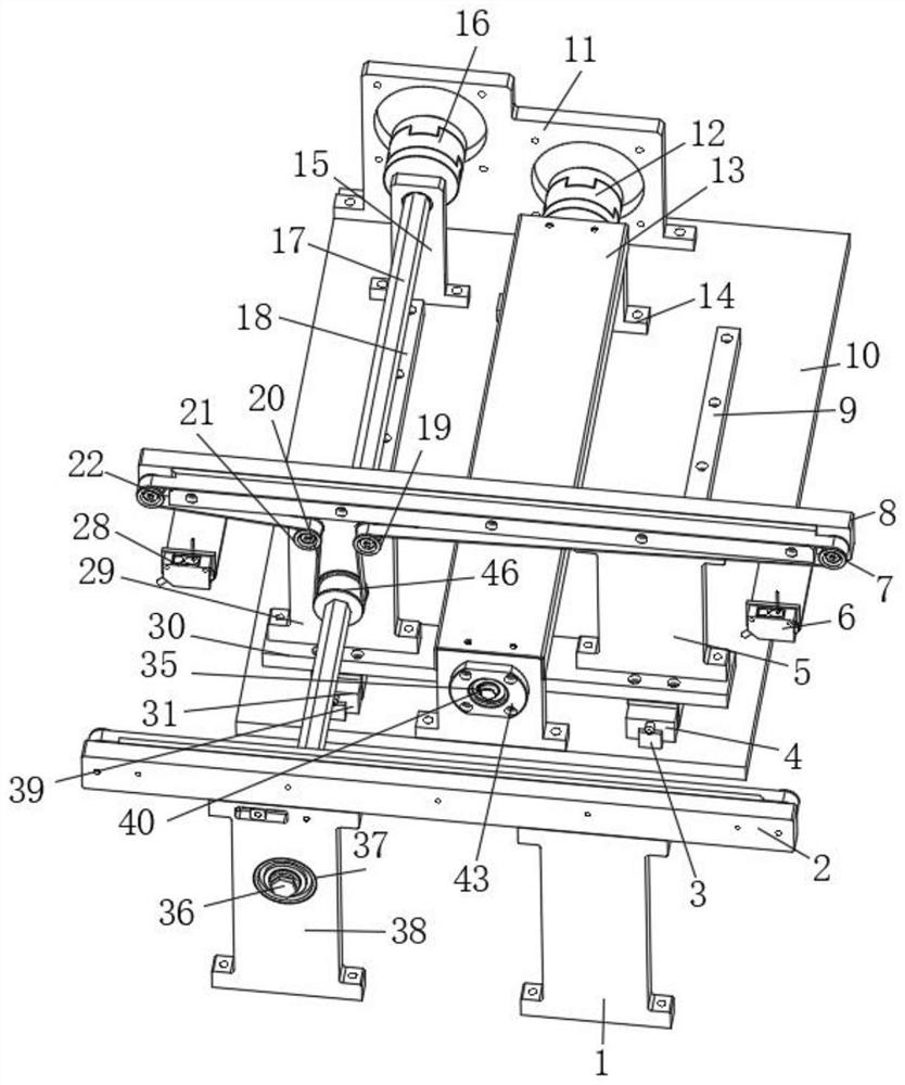
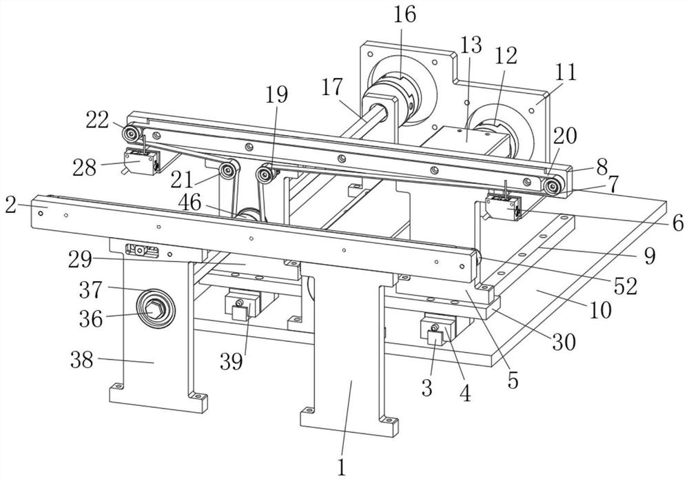
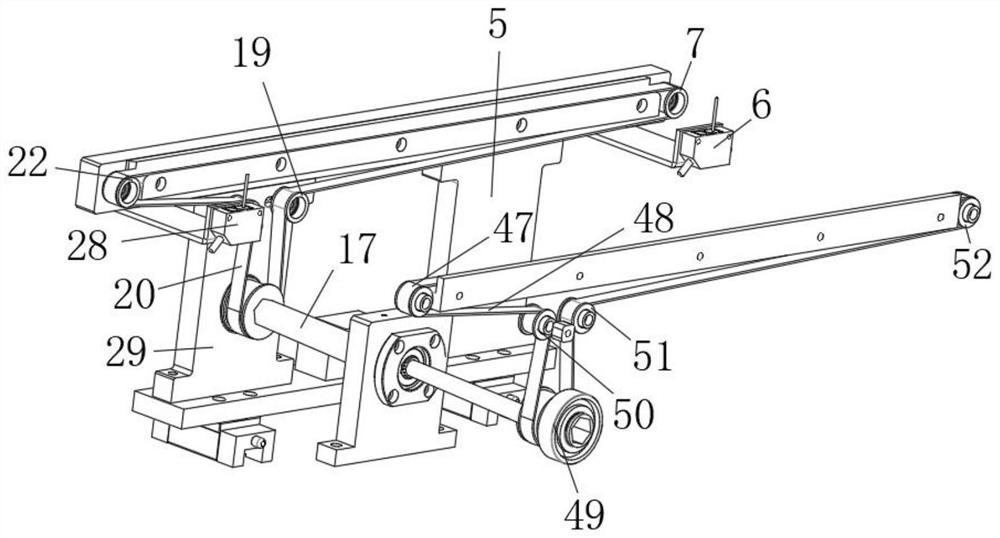
[0040] Such as Figure 1-11 As shown, the adjustable assembly line bed includes a first leg support board 1, a first slide rail 2, a first clamp block 4, a second leg support board 5, a first button module 6, a first buffer pillow 9, a first One upper transmission auxiliary shaft 7, load-bearing bottom plate 10, transmission shaft housing 13, first support plate 14, second support plate 15, the upper end of the first leg support plate 1 is provided with the first slide rail 2, the first slide rail 2 The lower end is provided with a clamping plate 3, and one end of the clamping plate 3 is provided with a first clamping block 4, and one end of the first clamping block 4 is provided with a second leg support plate 5, and the upper end of the second leg support plate 5 is provided with a first button mold. Group 6, the upper end of the first button module 6 is provided with a first upper transmission subshaft 7, one end of the first upper transmission subshaft 7 is provided with a...
Embodiment 2
[0050] The method of using the adjustable assembly line bed, the steps of the method of use are as follows:
[0051] Step 1: Connect the external driving source with the first driving module 12 and the second driving module 16, and then drive the rotation of the first driving module 12 and the second driving module 16;
[0052] Step 2: The rotation of the first driving module 12 drives the rotation of the first transmission shaft 35 at one end, the rotation of the second driving module 16 drives the rotation of the second transmission shaft 17 at one end, and the rotation of the second transmission shaft 17 Drive the operation of the first main transmission shaft 46 at one end, and then drive the operation of the first 20 through the rotation of the first main transmission shaft 46, and then drive the first upper transmission countershaft 7 and the second upper transmission pair through the rotation of the first transmission belt 20 The rotation of the shaft 19, the third uppe...
Embodiment 3
[0056] Working principle: connect the external adjustable assembly line bed with the first driving module 12 and the second driving module 16, and then drive the rotation of the first driving module 12 and the second driving module 16, and pass the first driving module The rotation of the group 12 further drives the rotation of the first transmission shaft 35 at one end, and the rotation of the second drive module 16 further drives the rotation of the second transmission shaft 17 at one end, and the rotation of the second transmission shaft 17 drives the first main transmission shaft 46 at one end. The rotation of the first main transmission shaft 46 further drives the operation of the first 20, and the rotation of the first transmission belt 20 further drives the first upper transmission countershaft 7, the second upper transmission countershaft 19, and the third upper transmission countershaft The rotation of the shaft 21 and the fourth upper transmission countershaft 22 driv...
PUM
 Abstract
Description
Claims
Application Information
 - R&D
- Intellectual Property
- Life Sciences
- Materials
- Tech Scout
- Unparalleled Data Quality
- Higher Quality Content
- 60% Fewer Hallucinations
Browse by: Latest US Patents, China's latest patents, Technical Efficacy Thesaurus, Application Domain, Technology Topic, Popular Technical Reports.
© 2025 PatSnap. All rights reserved.Legal|Privacy policy|Modern Slavery Act Transparency Statement|Sitemap|About US| Contact US: help@patsnap.com


