Medical fiber material preparation machine

A fiber material and preparation machine technology, which is applied in the cutting of textile materials, textiles and papermaking, metal processing, etc., can solve the problems of difficult to remove the surface of finished medical fiber cotton cloth, and achieve the effect of avoiding the accelerated cutting speed.

Inactive Publication Date: 2021-09-03
蔡彬彬
View PDF0 Cites 0 Cited by
  • Summary
  • Abstract
  • Description
  • Claims
  • Application Information

AI Technical Summary

Problems solved by technology

[0003] Due to the fluffy texture of the medical fiber cotton cloth, if the cutting speed of the medical fiber cotton cloth is fast by the knife of the medical fiber material cutting machine, it is easy to cause the cut surface of the medical fiber cotton cloth to be closely attached to the knife surface and be quickly brought. so that the guillotine will lift up the lint on the cut surface of the cotton cloth. If this happens for a long time, the surface of the finished medical fiber cotton cloth will be covered by the lint that is difficult to remove.

Method used


Image

  • Medical fiber material preparation machine
  • Medical fiber material preparation machine
  • Medical fiber material preparation machine

Examples


Embodiment 1

[0028] For example figure 1 -example Figure 5 Shown:

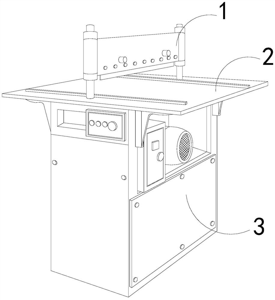
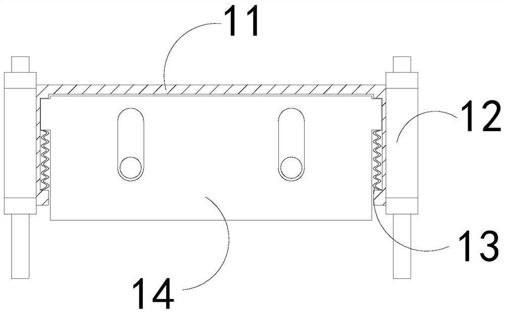
[0029] The present invention provides a medical fiber material preparation machine, the structure of which includes a cutting mechanism 1, an operating table 2, and a base 3, the bottom of the operating table 2 is welded to the top of the base 3, and the cutting mechanism 1 is installed on the operating table 2; the cutting mechanism 1 includes a frame 11, a support rod 12, a pullback bar 13, and a knife 14. The frame 11 is embedded between two support rods 12, and the pullback bar 13 is installed on Between the switch knife 14 and the inner wall of the frame 11 , the switch knife 14 is movably engaged with the inner wall of the frame 11 .

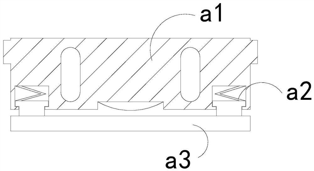
[0030] Wherein, the switch knife 14 includes a blade surface a1, an elastic piece a2, and a cutting piece a3. The elastic piece a2 is installed on the upper end of the inner wall of the knife surface a1 and the top position of the cutting piece a3. The inner wall of the inner wall ...

Embodiment 2

[0036] For example Image 6 -example Figure 9 Shown:

[0037]Wherein, the knife surface a1 includes a connecting strip c1, a receiving plate c2, a force receiving block c3, and a buffer piece c4. The connecting bar c1 is installed between the upper end of the force receiving block c3 and the upper end of the inner wall of the receiving plate c2. The force-bearing block c3 cooperates with the inner wall of the receiving plate c2, and the buffer sheet c4 is fixed on the inner wall of the receiving plate c2. The buffer sheet c4 adopts an arc-shaped convex structure made of spring steel, and the buffer sheet c4 can The impact force when the stressed block c3 shrinks is buffered.

[0038] Wherein, the force receiving block c3 includes an upper connection plate c31, a suction block c32, a lower swing plate c33, and a suction block c34. The suction block c32 is embedded in the inner position of the lower swing plate c33, and the lower swing plate c33 and the suction block The bot...


PUM


Abstract

The invention discloses a medical fiber material preparation machine. The medical fiber material preparation machine structurally comprises a cutting mechanism, an operating floor and a base, the bottom of the operating floor is welded to the top of the base, the cutting mechanism is installed at the top position of the operating floor, and a movable ball can rotate through friction generated by the tangent plane of medical fiber cotton cloth to the movable ball, so that a cutting blade can smoothly cut off medical fiber cotton cloth; then an external expansion plate can extend outwards through thrust generated by a boosting blade to the external expansion plate, and therefore the section of the medical fiber cotton cloth can be pushed away from the surface of a knife switch; and the cutting blade contracts upwards to extrude the stress block, the stress block can be contracted upwards along a bearing plate, so that the contracted stress block can be buffered by a buffer plate, and then the cutting blade can be pressed by a lower pressing plate, so that the medical fiber cotton cloth can be better cut off by the cutting blade.

Description

technical field [0001] The invention relates to the field of fiber and composite material preparation, in particular to a medical fiber material preparation machine. Background technique [0002] The medical fiber material cutting machine is mainly used for cutting the medical fiber material. By placing the medical fiber material on the operating table, and then passing through the knife above the operating table, the medical fiber material can be cut. , widely used in industries such as medical fiber cotton cutting, based on the above description, the inventors found that the existing medical fiber material preparation machine mainly has the following deficiencies, for example: [0003] Due to the fluffy texture of the medical fiber cotton cloth, if the cutting speed of the medical fiber cotton cloth is fast by the knife of the medical fiber material cutting machine, it is easy to cause the cut surface of the medical fiber cotton cloth to be closely attached to the knife su...

Claims


Application Information

Patent Timeline
Patent Type & Authority Applications(China)
IPC IPC(8): D06H7/00B26D1/08B26D7/01B26D7/18
CPCD06H7/00B26D1/085B26D7/015B26D7/1818
Inventor 蔡彬彬
Owner 蔡彬彬
Why Eureka
Try Eureka