A high stability single crystal silicon differential pressure sensor
What is AI technical title?
AI technical title is built by Patsnap AI team. It summarizes the technical point description of the patent document.
A high-stability, single-crystal silicon technology, applied in the field of sensors, can solve problems such as difficult removal of parts, and achieve the effect of expanding the cavity capacity
Active Publication Date: 2022-07-19
安徽允昊物联网科技有限公司
View PDF8 Cites 0 Cited by
Summary
Abstract
Description
Claims
Application Information
AI Technical Summary
This helps you quickly interpret patents by identifying the three key elements:
Problems solved by technology
Method used
Benefits of technology
Problems solved by technology
[0003] The accommodation space on the pressure chamber of the high-stability monocrystalline silicon differential pressure sensor is filled with pressure-guiding medium, and the sensing block of the device will be worn out during long-term use, and the pressure-guiding medium is easy to expand and contract due to temperature , if there is a crack in the wear of the sensing block, the pressure-guiding medium will be sprayed out through the damaged crack of the sensing block, and it is difficult to remove when it adheres to other parts of the equipment
Method used
Image
Click on the blue label to locate the original text in one second.
Reading with bidirectional positioning of images and text.
Examples
Embodiment 1
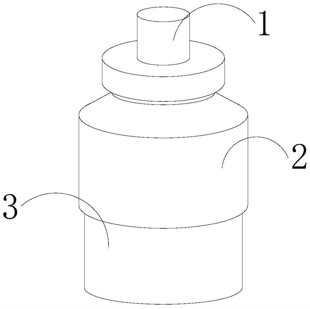
[0027] see Figure 1-Figure 5 , a high stability single crystal silicon differential pressure sensor, its structure includes a connector 1, an operation box 2, a base 3, the operation box 2 is provided with a connector 1, and the connector 1 is movably connected to the operation box 2 , the base 3 is installed on the operation box 2, and the operation box 2 is connected to the base 3;
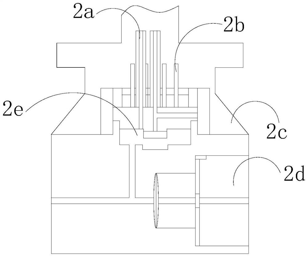
[0028] The operation box 2 is provided with an oil filling pipe 2a, an electrical block 2b, a box body 2c, a pressure chamber 2d, and an operator 2e. The box body 2c is provided with an oil filling pipe 2a inside, and the oil filling pipe 2a is embedded in the box body 2c. In combination, the electrical block 2b is installed on the box body 2c, the box body 2c is movably connected to the electrical block 2b, the operator 2e is installed on the box body 2c, and the box body 2c is in phase with the operator 2e The pressure chamber 2d is installed inside the box body 2c, and the box body 2c is mo...
Embodiment 2
[0036] see Figure 1-Figure 6 , a high stability single crystal silicon differential pressure sensor, its structure includes a connector 1, an operation box 2, a base 3, the operation box 2 is provided with a connector 1, and the connector 1 is movably connected to the operation box 2 , the base 3 is installed on the operation box 2, and the operation box 2 is connected to the base 3;
[0037] The operation box 2 is provided with an oil filling pipe 2a, an electrical block 2b, a box body 2c, a pressure chamber 2d, and an operator 2e. The box body 2c is provided with an oil filling pipe 2a inside, and the oil filling pipe 2a is embedded in the box body 2c. In combination, the electrical block 2b is installed on the box body 2c, the box body 2c is movably connected to the electrical block 2b, the operator 2e is installed on the box body 2c, and the box body 2c is in phase with the operator 2e The pressure chamber 2d is installed inside the box body 2c, and the box body 2c is mo...
PUM
Abstract
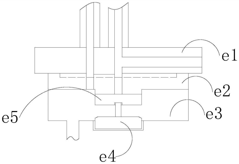
The invention discloses a single crystalsilicondifferential pressure sensor with high stability. The operation box is connected to the base. The operation box is provided with an oil filling pipe, an electrical block, a box body, a pressure chamber and an operator. An oil filling pipe is arranged inside the box body. The oil filling pipe is fitted with the box body, and the electrical block is installed in the box body. On the upper side, the box body is movably connected with the electrical block. If the sensor block is replaced in the present invention, the sensor block will pull the occluder during the process of taking out the sensor block. When the occluder is pulled, it will leave the recess on the medium box Due to the increase of the medium volume, the pressure guiding medium will flow into the groove of the medium box first, and the medium will not be ejected from the installation opening when the sensor block is taken out.
Description
technical field [0001] The invention relates to the field of sensors, in particular to a high-stability single-crystalsilicondifferential pressure sensor. Background technique [0002] The high-stability single-crystalsilicondifferential pressure sensor is a detection device that can sense the measured information, and can transform the sensed information into electrical signals or other required forms of information output according to certain rules to meet the needs of the information. requirements for transmission, processing, storage, display, recording and control; [0003] The accommodating space on the pressure cavity of the high-stability single-crystal silicon differential pressure sensor is filled with a pressure-conducting medium, and the sensing block of the device will be worn out during long-term use, and the pressure-conducting medium is susceptible to thermal expansion and contraction due to temperature. , If the wear of the sensing block has a crack, th...
Claims
Application Information
Patent Timeline
Application Date:The date an application was filed.
Publication Date:The date a patent or application was officially published.
First Publication Date:The earliest publication date of a patent with the same application number.
Issue Date:Publication date of the patent grant document.
PCT Entry Date:The Entry date of PCT National Phase.
Estimated Expiry Date:The statutory expiry date of a patent right according to the Patent Law, and it is the longest term of protection that the patent right can achieve without the termination of the patent right due to other reasons(Term extension factor has been taken into account ).
Invalid Date:Actual expiry date is based on effective date or publication date of legal transaction data of invalid patent.

