
Positioning mounting clamp for metal part machining

A technology for positioning, installation, and parts, which is applied in the field of parts processing, and can solve problems such as automatic stamping, low degree of automation, and lack of linkage

Inactive Publication Date: 2021-09-07
曾凡春
View PDF0 Cites 4 Cited by
  • Summary
  • Abstract
  • Description
  • Claims
  • Application Information

AI Technical Summary

Problems solved by technology

[0005] Aiming at the deficiencies of the prior art, the present invention provides a positioning and mounting clamp for metal parts processing, which has the advantages of automatic feeding, automatic stamping, self-adaptive clamping, clean stamping die, linkage between structures, and a high degree of automation , which solves the problems that the existing device cannot automatically feed materials, cannot automatically stamp, cannot self-adaptive clamping, cannot clean the stamping die, has no linkage between structures, and has a low degree of automation

Method used


Image

  • Positioning mounting clamp for metal part machining
  • Positioning mounting clamp for metal part machining
  • Positioning mounting clamp for metal part machining

Examples


Embodiment Construction

[0029] The following will clearly and completely describe the technical solutions in the embodiments of the present invention with reference to the accompanying drawings in the embodiments of the present invention. Obviously, the described embodiments are only some, not all, embodiments of the present invention. Based on the embodiments of the present invention, all other embodiments obtained by persons of ordinary skill in the art without making creative efforts belong to the protection scope of the present invention.

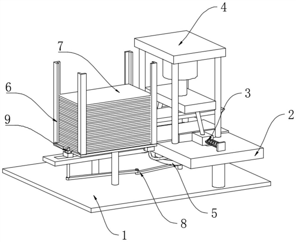
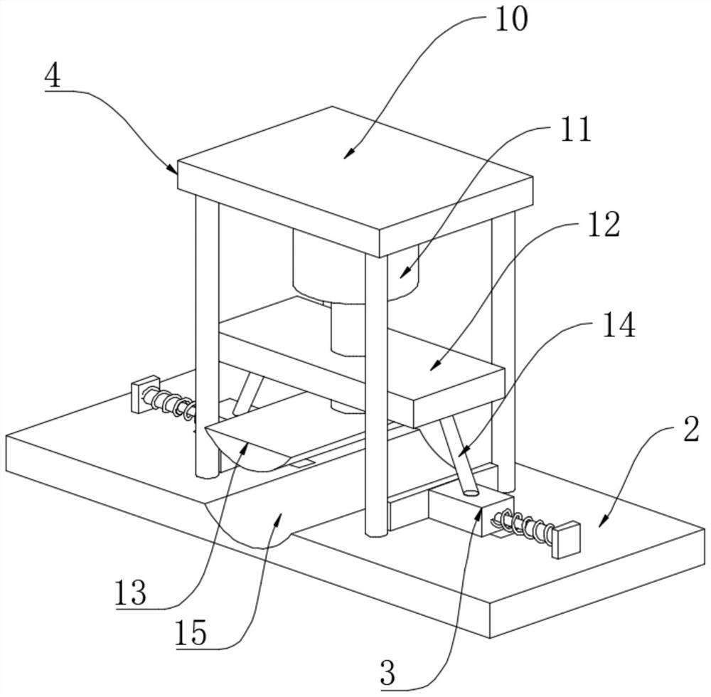
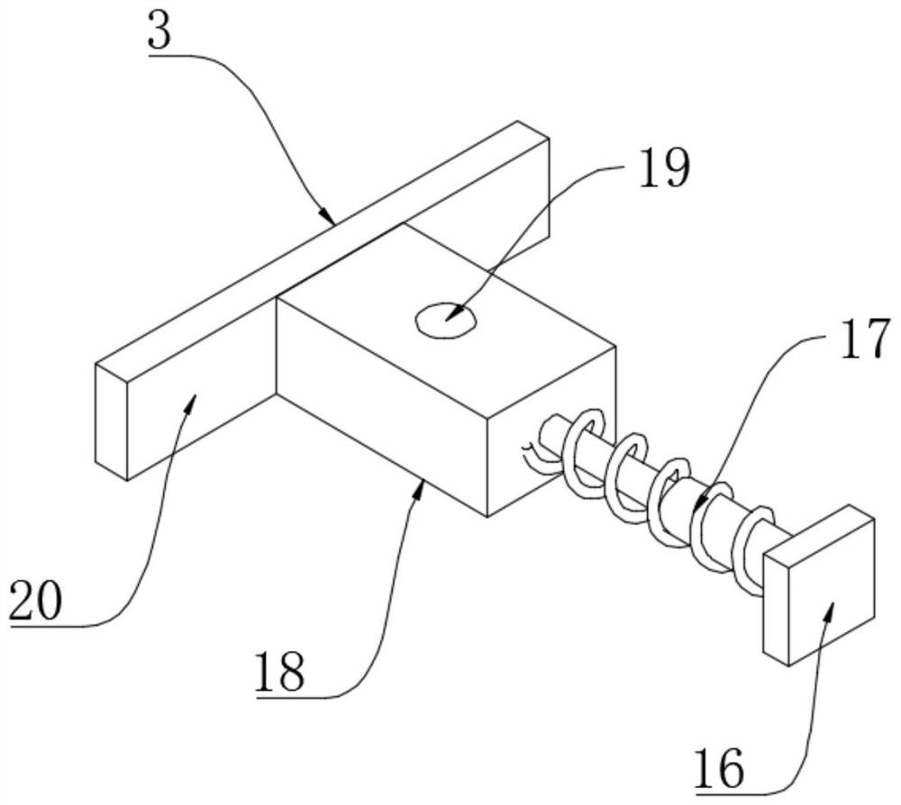
[0030] see Figure 1-8, a positioning mounting clip for processing metal parts, including a mounting base 1, a processing table 2 is fixedly installed on the top right side of the mounting base 1, a stamping device 4 is fixedly installed on the top of the processing table 2, and the middle of the top of the processing table 2 There is a stamping seat 15 in the position, and the top of the processing table 2 is movably connected with the limit device 3 relative...


PUM


Abstract

The invention relates to the technical field of part machining, and discloses a positioning mounting clamp for metal part machining, which comprises a mounting base; a machining table is fixedly mounted on the right side of the top of the mounting base; a stamping device is fixedly mounted on the top of the machining table; a stamping seat is arranged in the middle of the top of the machining table; limiting devices are movably connected to the positions, opposite to the front side and the rear side of the stamping base, of the top of the machining table correspondingly; and a cleaning device is arranged at the bottom of the machining table. According to the positioning mounting clamp for the metal part machining provided by the invention, a metal plate is continuously stamped by setting the stamping device, in the stamping process, the limiting devices are driven to conduct self-adaptive clamping on the metal plate, the metal plate is prevented from loosening, meanwhile, the cleaning device is driven to conduct air injection cleaning on the stamping seat, the stamping precision is prevented from being affected, meanwhile, a feeding device is driven to conduct continuous feeding, the work efficiency of stamping forming is improved, linkage is achieved between structures, and the automation degree is high.

Description

technical field [0001] The invention relates to the technical field of parts processing, in particular to a positioning mounting clip for processing metal parts. Background technique [0002] The stamping forming process is often used in the processing of metal parts. Stamping forming refers to the application of external force to plates, strips, pipes and profiles by presses and molds to cause plastic deformation or separation to obtain workpieces of the required shape and size. (stamping parts) processing and forming methods. The blanks for stamping are mainly hot-rolled and cold-rolled steel sheets and strips. Among the steel products in the world, 60-70% are plates, most of which are stamped into finished products. The body, chassis, fuel tank, radiator fins of the car, the steam drum of the boiler, the shell of the container, the iron core silicon steel sheet of the motor and electrical appliances, etc. are all stamped. There are also a large number of stamping parts...

Claims


Application Information

Patent Timeline
Patent Type & Authority Applications(China)
IPC IPC(8): B21D43/00B21D43/22B21D22/02B08B5/02B21D43/24
CPCB21D43/003B21D43/22B21D22/02B08B5/02B21D43/24
Inventor 曾凡春
Owner 曾凡春
Learn More