Supercharge Your Innovation With Domain-Expert AI Agents!

Elevator counterweight frame assembling structure

A technology of assembly structure and frame structure, which is applied in transportation and packaging, lifting equipment in mines, etc. It can solve problems such as the difficulty of neatly installing heavy blocks into the bottom of the frame, reducing the load-bearing tension of side beams, and difficult installation of heavy blocks. , to achieve the effect of reducing handling risk, reducing labor intensity and strengthening stability

Inactive Publication Date: 2021-09-07
重庆市华创电梯部件有限公司
View PDF6 Cites 0 Cited by
  • Summary
  • Abstract
  • Description
  • Claims
  • Application Information

AI Technical Summary

Problems solved by technology

[0003] In the existing elevator counterweight frame, the structure of the side beam is produced by a flat plate through punching, bending and other processes. For some relatively long counterweight frame side beams, especially the high-speed ladder type counterweight The frame side beams require a very large processing length. When installing the counterweights on the counterweight frame of such extended side beams, it is difficult to neatly install the counterweights into the bottom of the frame, making the installation of the counterweights difficult.
[0004] There are some existing counterweight frame side beam structures, which achieve quick installation of the counterweight by opening square holes on the side beam, but when the length of the counterweight frame side beam is long, although it is convenient to install the counterweight, due to the internal The added counterweight is heavy, and the gap opened by the side beam will reduce the load-bearing tension of the side beam, causing the side beam to deform at the gap, resulting in a dangerous situation

Method used


Image

  • Elevator counterweight frame assembling structure
  • Elevator counterweight frame assembling structure
  • Elevator counterweight frame assembling structure

Examples


Embodiment

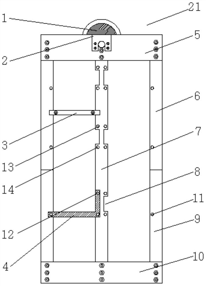
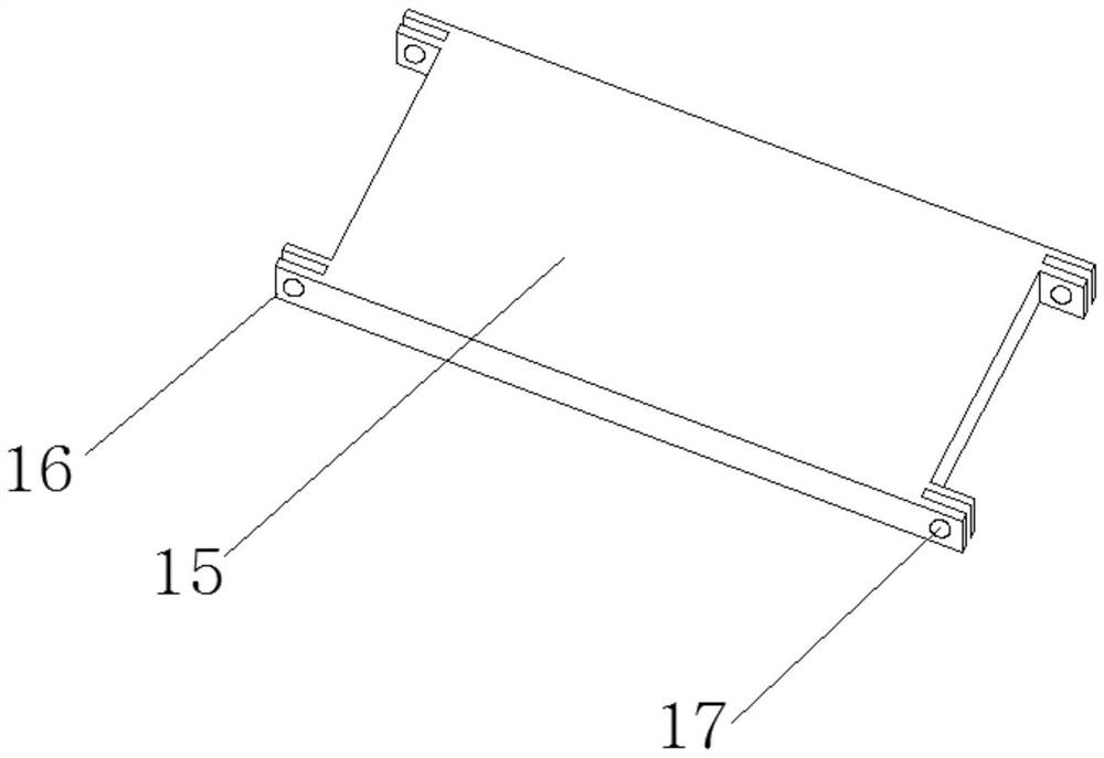
[0023] see Figure 1-5 , the present invention provides the following technical solutions: an elevator counterweight frame assembly structure, including a frame structure 21, a counterweight side fixing part 4 and a counterweight top fixing part 3, the frame structure 21 including a top beam 5, a top beam 5 Side beam assemblies are arranged on both sides, bottom beam 10 is arranged at the bottom of side beam assembly, top beam 5, side beam assembly and bottom beam 10 are all fastened by bolts, rope pulley 1 is installed inside top beam 5, side beam The middle beam 7 is fixed between the components, and the middle beam 7 is fixed between the top beam 5 and the bottom beam 10 by bolts. There is a counterweight installation opening 8 on one side of the middle beam 7, and a second counterweight installation opening 8 is opened on the top of the counterweight installation opening 8. A bolt hole 13, a second bolt hole 14 is provided at the bottom of the counterweight installation po...


PUM


Abstract

The invention belongs to the technical field of elevator counterweight frames, and particularly relates to an elevator counterweight frame assembling structure. The elevator counterweight frame assembling structure comprises a frame structure, counterweight block side face fixing pieces and counterweight block top face fixing pieces, the frame structure comprises a top beam, side beam assemblies are arranged on the two sides of the top beam, and a bottom beam is arranged at the bottoms of the side beam assemblies. The top beam, the side beam assemblies and the bottom beam are fastened through bolts, a rope wheel is installed in the top beam, a middle beam is fixed between the side beam assemblies, the middle beam is fixed between the top beam and the bottom beam through bolts, so that the size of a single corresponding counterweight block is reduced, workers can conveniently carry the counterweight block, the counterweight block is quickly mounted in a counterweight frame, so that the labor intensity is reduced, the carrying risk is reduced, the bearing capacity of side beams is increased, and the dangerous deformation condition of the side beams is avoided; and meanwhile, a counterweight mounting opening is sealed by using a counterweight side fixing piece, so that the stability of the counterweight block is enhanced from the side surface while the middle beam is reinforced.

Description

technical field [0001] The invention belongs to the technical field of an elevator counterweight frame, and in particular relates to an assembly structure of an elevator counterweight frame. Background technique [0002] Elevator counterweight is a method of maintaining balance between the weight of the car and the payload portion. Counterweight to reduce energy consumption and motor power loss. In addition, on hoists with rope drive pulleys, the counterweight maintains the required stress ratio between the car and the rope branches on one side of the counterweight, in order to obtain proper friction between the rope and the rope drive pulley groove force. [0003] In the existing elevator counterweight frame, the structure of the side beam is produced by a flat plate through punching, bending and other processes. For some relatively long counterweight frame side beams, especially the high-speed ladder type counterweight The frame side beams require a very large processin...

Claims


Application Information

Patent Timeline
Patent Type & Authority Applications(China)
IPC IPC(8): B66B17/12
CPCB66B17/12
Inventor 李铮
Owner 重庆市华创电梯部件有限公司
Features
  • R&D
  • Intellectual Property
  • Life Sciences
  • Materials
  • Tech Scout
  • Unparalleled Data Quality
  • Higher Quality Content
  • 60% Fewer Hallucinations
Learn More