
Bridge construction method and bridge structure

A bridge structure and bridge technology, applied in the direction of bridges, bridge parts, bridge construction, etc., can solve the problems of reducing bridge stability, bridge vibration, poor shock absorption effect, etc., to reduce metal fatigue strength, increase load capacity, and reduce load The effect of intensity

Inactive Publication Date: 2021-09-07
陈颖
View PDF0 Cites 0 Cited by
  • Summary
  • Abstract
  • Description
  • Claims
  • Application Information

AI Technical Summary

Problems solved by technology

[0004] The purpose of the present invention is: in order to meet the needs of the modern transportation industry, the span of bridge construction is getting larger and larger, resulting in more prominent flexibility of the bridge, mainly adopting a full-floating or semi-floating system, in temperature, wind load, Under the action of live loads such as vehicle loads, the bridge will vibrate, resulting in lateral displacement of the beam body of the upper structure of the bridge, reducing the stability of the bridge, and posing potential safety hazards. Spring is used to achieve this. Since the elastic coefficient of the spring is constant, the vibration frequency generated by the bridge will change due to the different forces it receives, resulting in the problem of poor shock absorption. A bridge construction method and bridge structure are proposed.

Method used


Image

  • Bridge construction method and bridge structure
  • Bridge construction method and bridge structure
  • Bridge construction method and bridge structure

Examples


Embodiment Construction

[0041] The following will clearly and completely describe the technical solutions in the embodiments of the present invention with reference to the accompanying drawings in the embodiments of the present invention. Obviously, the described embodiments are only some, not all, embodiments of the present invention. Based on the embodiments of the present invention, all other embodiments obtained by persons of ordinary skill in the art without creative efforts fall within the protection scope of the present invention.

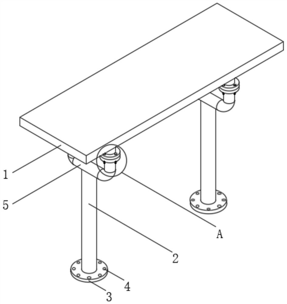
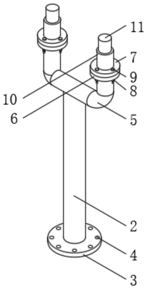
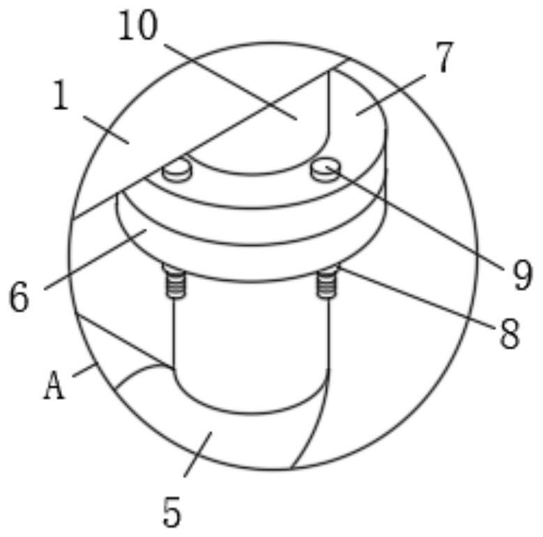
[0042] see Figure 1-5 , the present invention provides a technical solution: a bridge structure, including a bridge body 1, a bridge pier column 2 is arranged below the bridge body 1, and a bridge-type connecting frame 5 is fixedly connected to one end of the bridge pier column 2 close to the bridge body 1, One end of the bridge connecting frame 5 close to the bridge main body 1 is fixedly connected with a lower connecting platform 6, and one side of the lower con...


PUM


Abstract

The invention discloses a bridge construction method and a bridge structure, and belongs to the technical field of bridge construction. The bridge structure comprises a bridge body, a bridge pier column is arranged below the bridge body, and the end, close to the bridge body, of the bridge pier column is fixedly connected with a bridge type connecting frame; the end, close to the bridge body, of the bridge-shaped connecting frame is fixedly connected with a lower-layer connecting platform. According to the method, through mutual cooperation of structures such as the damping support, the damping inner shaft, the supporting spring, the tooth-shaped plate, the insection surface, the adapter shaft, the winding coil, a permanent magnet base, the permanent magnet and the electromagnet, the multi-frequency-band buffer effect can be achieved, the buffer effect can be achieved, and the buffer force of the supporting spring can be assisted through the magnetic force effect, the load strength of the supporting spring is reduced, the metal fatigue strength of the supporting spring is relieved, the damping coefficient under buffering is automatically changed according to the change of the vibration frequency generated when the bridge body is subjected to external force, and deviation from a preset frequency sensitive area can be effectively avoided.

Description

technical field [0001] The invention belongs to the technical field of bridge construction, and in particular relates to a bridge construction method and a bridge structure. Background technique [0002] Bridges generally refer to structures erected on rivers, lakes, and seas to allow vehicles and pedestrians to pass smoothly. In order to adapt to the modern high-speed development of the transportation industry, bridges are also extended to cross mountains, poor geology, or meet other traffic needs to make traffic more convenient. Bridges are generally composed of superstructure, substructure, supports and auxiliary structures. The superstructure is also called bridge span structure, which is the main structure for crossing obstacles. The substructure includes abutments, piers and foundations. The force transmission device installed at the support of the span structure and the bridge pier or bridge abutment, and the auxiliary structures refer to the bridge head board, conica...

Claims


Application Information

Patent Timeline
IPC IPC(8): E01D19/00E01D21/00
CPCE01D19/00E01D21/00
Inventor 陈颖刘强
Owner 陈颖
Learn More