
Transient control method and device for Variable valve timing system and Miller cycle engine

A technology of valve timing and control method, applied in combustion engine, engine control, machine/engine, etc., can solve the problem of not giving, increase the calibration work, increase the burden of the controller, etc., to achieve the effect of good driving experience

Active Publication Date: 2021-09-07
CHONGQING CHANGAN AUTOMOBILE CO LTD
View PDF16 Cites 4 Cited by
  • Summary
  • Abstract
  • Description
  • Claims
  • Application Information

AI Technical Summary

Problems solved by technology

Although this method can theoretically improve the transient response of the engine, it does not provide the switching control between steady-state VVT ​​control and transient VVT control, and cannot solve the aforementioned drivability problem of torque drop; and this method is to deal with two sets of VVT strategies. Need to add two sets of inflation models, two sets of torque models and two sets of software strategies for ignition angle control, which greatly increases the burden on the controller; it also involves two sets of VVT strategy calibration, two sets of ignition angle calibration, and two sets of inflation model calibration And the calibration of two sets of torque models, etc., need to increase a lot of calibration work

Method used


Image

  • Transient control method and device for Variable valve timing system and Miller cycle engine
  • Transient control method and device for Variable valve timing system and Miller cycle engine
  • Transient control method and device for Variable valve timing system and Miller cycle engine

Examples


Embodiment Construction

[0022] The specific implementation of the application will be further described below in conjunction with the accompanying drawings. The implementation of the application is not limited by the following methods, as long as the method concept and technical solutions of the application are adopted. The direct application of ideas and technical solutions to other occasions is within the protection scope of this application.

[0023] In order to facilitate understanding of the technical solution of the present application, the background technology of the technical solution of the present application is briefly described below.

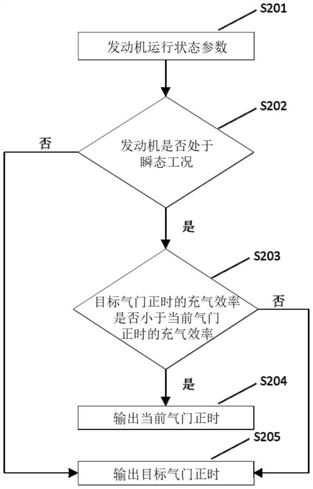
[0024] Based on the drivability problems of slow torque transient response and torque drop pits mentioned in the background technology, the present invention provides a transient control method for a variable valve timing system of a Miller cycle engine, see figure 2 , the concrete steps of the inventive method are as follows:

[0025] S201, acquiring e...


PUM


Abstract

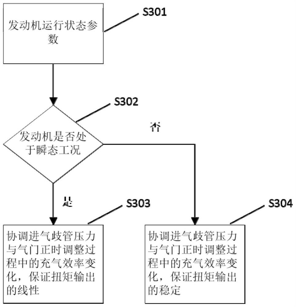
The invention provides a transient control method and device for a variable valve timing system and a Miller cycle engine, and the method comprises the following steps: 1, judging whether an engine enters a transient working condition or not according to obtained engine operation state parameters; 2, determining target valve timing according to the rotating speed and the target load, and judging whether the inflation efficiency of the target valve timing is smaller than the inflation efficiency of the current valve timing or not; 3, keeping the current valve timing unchanged; and 4, adjusting valve timing to the target position, in the valve timing adjusting process, according to different operation states of the engine, coordinating the inflation efficiency change caused by the pressure of the intake manifold and the valve timing change, and achieving different torque output characteristics. The invention aims to at least solve the drivability problems of slow torque transient response and torque pit falling mentioned in the background technology.

Description

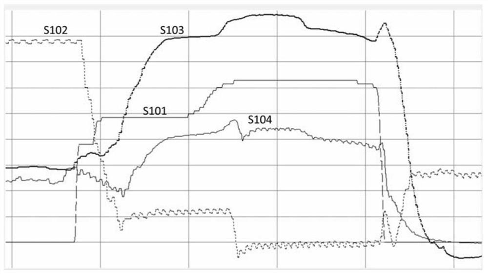
technical field [0001] The invention relates to the technical field of engines, in particular to variable valve timing control technology for Millerson cycle engines. Background technique [0002] As the market demands higher and higher fuel economy, Miller cycle technology is more and more widely used in gasoline engines. The Miller cycle is to control the intake air volume, the end-of-compression temperature and pressure of the gas in the cylinder by adjusting the closing time of the intake valve, thereby reducing the effective compression ratio of the engine, and obtaining a thermodynamic cycle mode in which the expansion ratio is greater than the effective compression ratio. Miller cycle engines are usually combined with high compression ratio technology, which can effectively improve the theoretical thermal efficiency of the engine and achieve a significant increase in fuel economy. [0003] Such as figure 1 As shown, in the process of pursuing the ultimate fuel consu...

Claims


Application Information

Patent Timeline
Patent Type & Authority Applications(China)
IPC IPC(8): F02D13/02
CPCF02D13/0223Y02T10/12
Inventor 何建华胡铁刚蒋平
Owner CHONGQING CHANGAN AUTOMOBILE CO LTD
Learn More