
Automatic peeling device

An automatic, skin-based technology, applied to cable installation devices, cable installation, equipment for dismantling/armored cables, etc., can solve problems such as high cost, damaged inner core, and inability to completely peel off the wire skin

Pending Publication Date: 2021-09-07
深圳市明源鑫机械有限公司
View PDF1 Cites 1 Cited by
  • Summary
  • Abstract
  • Description
  • Claims
  • Application Information

AI Technical Summary

Problems solved by technology

In the cable wire laser stripping mechanism, although it is not necessary to manually hold the cable for operation, which improves the processing efficiency, the laser stripping mechanism still has certain defects.
In the actual production process of electronic wire rods, the inner core of the wire rod cannot be guaranteed to be completely located in the center of the wire rod, and it is easy to have a certain offset; that is to say, the thickness of the skin on the four sides of the inner core is not consistent, which means As a result, when the above cable and wire laser stripping mechanism is used for peeling, if the cutting depth of the peeling is too deep, the inner core will be damaged, and if the cutting depth of the peeling is too shallow, the wire skin cannot be completely peeled off, and the cost of laser peeling is higher.

Method used


Image

  • Automatic peeling device
  • Automatic peeling device
  • Automatic peeling device

Examples


Embodiment Construction

[0027] In order to make the object, technical solution and advantages of the present invention clearer, the present invention will be further described in detail below in conjunction with the accompanying drawings and embodiments. It should be understood that the specific embodiments described here are only used to explain the present invention, not to limit the present invention.

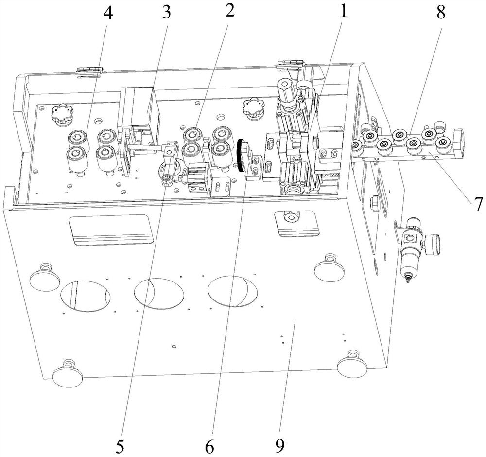
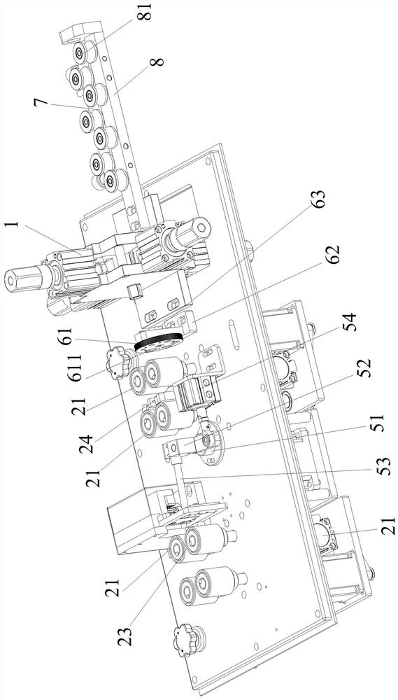
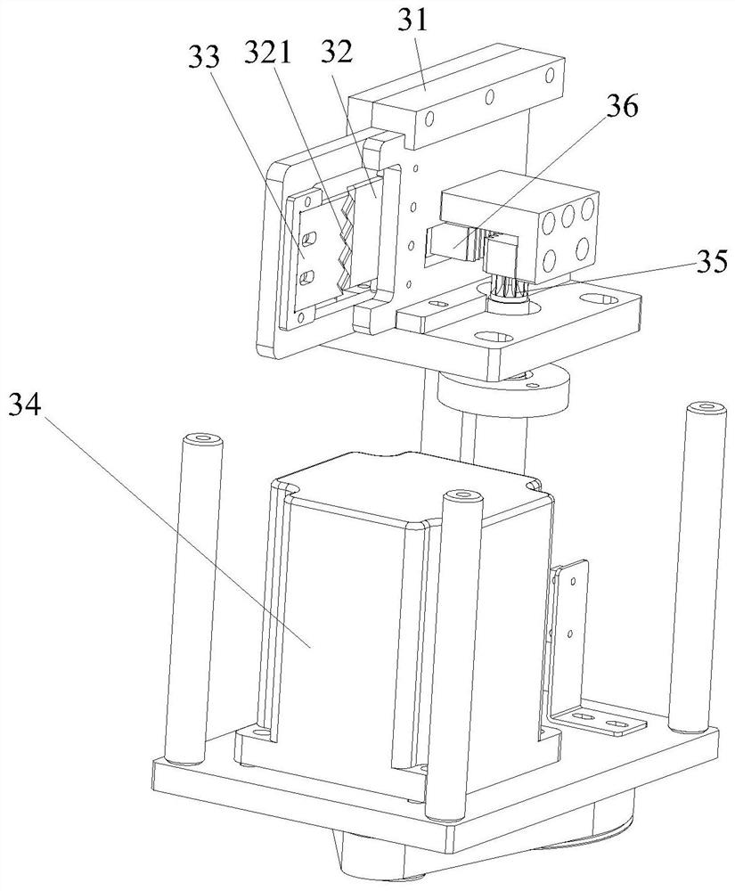
[0028] see Figure 1-4 , an automatic peeling device, characterized in that the device includes a cross-cutting mechanism 1 for laterally cutting the skin of the electronic wire, a first traction rolling mechanism 2 for pulling the electronic wire and rolling the electronic wire, and The vertical cutting mechanism 3 for vertically cutting the skin of the electronic wire, the second traction rolling mechanism 4 for pulling the electronic wire and rolling the electronic wire; the cross-cutting mechanism 1, the first traction rolling mechanism 2, the vertical The cutting mechanism 3 and the second tr...


PUM


Abstract

The invention belongs to the field of wire peeling, and particularly relates to an automatic peeling device. The peeling device is characterized in that the peeling device comprises a transverse cutting mechanism for transversely cutting the surface of an electronic wire, a first traction rolling mechanism for pulling the electronic wire and rolling the electronic wire, a vertical cutting mechanism which is used for vertically cutting the surface of the electronic wire rod, and a second traction rolling mechanism which is used for pulling the electronic wire rod and rolling the electronic wire rod; the transverse cutting mechanism, the first traction rolling mechanism, the vertical cutting mechanism and the second traction rolling mechanism are sequentially arranged, and a peeling path used for conducting traction peeling on the electronic wire is formed among the transverse cutting mechanism, the first traction rolling mechanism, the vertical cutting mechanism and the second traction rolling mechanism. According to the invention, the automatic stripping of the electronic wire can be realized, and the inner core of the electronic wire cannot be damaged while the smooth stripping of the wire skin can be ensured.

Description

technical field [0001] The invention belongs to the field of wire stripping, and in particular relates to an automatic stripping device. Background technique [0002] Electronic wire is a kind of electric energy or signal transmission device, usually composed of several or several groups of wires, and has a wide range of applications in modern society. Electronic wires often involve peeling operations. In the prior art, when peeling cables and wires, the operation is often carried out by manually holding the electronic wires. This is not only labor-intensive, but also easily causes damage to the inner core due to inaccurate alignment. [0003] In view of the above problems, the prior art provides a laser stripping mechanism for cables and wires (patent application number is CN202021729722.8), which has a loading station, a stripping station and a laser stripping machine located at the stripping station, including a loading platform, a transmission component and a clip The h...

Claims


Application Information

Patent Timeline
Patent Type & Authority Applications(China)
IPC IPC(8): H02G1/12
CPCH02G1/1263Y02W30/82
Inventor 杨爱明
Owner 深圳市明源鑫机械有限公司
Learn More