Controlling hydraulic actuating cylinders in roll stands

A rolling mill rack and regulating cylinder technology, applied in hydraulic program control, electric fluid pressure control, fluid pressure control, etc., can solve the problem of not considering the change in the performance of the regulating circuit, so as to prevent pressure drop and reliable hydraulic locking Effect

Pending Publication Date: 2021-09-07
SMS GRP GMBH
View PDF8 Cites 0 Cited by
  • Summary
  • Abstract
  • Description
  • Claims
  • Application Information

AI Technical Summary

Problems solved by technology

As a result, changes in the behavior of the control loop, such as the influence of possible valve wear under load on the stability of the control loop, are not taken into account

Method used


Image

  • Controlling hydraulic actuating cylinders in roll stands
  • Controlling hydraulic actuating cylinders in roll stands
  • Controlling hydraulic actuating cylinders in roll stands

Examples


Embodiment Construction

[0031] A preferred exemplary embodiment is described below with reference to the drawings. In this case, identical, similar or identically acting elements in different figures are provided with the same reference signs, and repeated descriptions of elements are partially omitted in order to avoid redundancy.

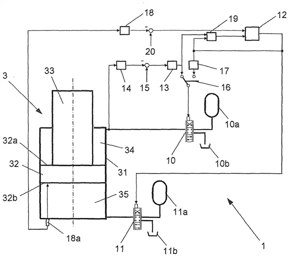
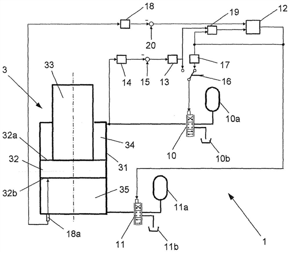
[0032] Figure 1a and Figure 1b is a schematic diagram of a hydraulic regulating circuit 1 for actuating a regulating cylinder 3 arranged for use in a rolling mill stand, Figure 1a It shows that the hydraulic regulating circuit is in the state of pressure regulation, Figure 1b The hydraulic regulating circuit is shown in a position regulating state.

[0033] The adjusting cylinder 3 is preferably an adjusting cylinder for an upright rolling stand, which has a cylindrical housing 31 in which a piston 32 is displaceably mounted. In this exemplary embodiment, the adjusting cylinder 3 has a piston rod 33 on the side of the piston 32, so that the piston 32 divides the ho...


PUM


Abstract

The invention relates to a hydraulic feedback control loop (1) for controlling a hydraulic actuating cylinder (3), in particular an adjustment cylinder for a working roll in a roll stand. The actuating cylinder comprises a cylindrical housing (31) and a piston (32) slidably arranged therein. The piston divides the housing interior into a first hydraulic chamber (34) and a second hydraulic chamber (35). The feedback control loop (1) comprises: at least one first hydraulic valve (10) which is designed to apply a hydraulic fluid to the first hydraulic chamber (34), wherein the hydraulic pressure of the first hydraulic chamber (34) can be adjusted by actuating the first hydraulic valve (10); at least one second hydraulic valve (11) which is designed to apply a hydraulic fluid to the second hydraulic chamber (35), wherein the hydraulic pressure of the second hydraulic chamber (35) can be adjusted by actuating the second hydraulic valve (11); an adjusting device (12-20) which is provided and designed for actuating the two hydraulic valves (10, 11) in order to actuate, in a position control state, the second hydraulic valve (11) by means of a position control signal dependent on the working position of the piston (32) and to actuate, in said position control state, the first hydraulic valve (10) by means of an adapted position control signal, which is a signal generated on the basis of the position control signal.

Description

technical field [0001] The invention relates to a hydraulic control circuit and a method for controlling a hydraulic control cylinder, in particular a control cylinder for work rolls in a rolling stand, preferably a vertical rolling stand. Background technique [0002] It is known to adjust the roll gap between two work rolls by means of hydraulic adjusting cylinders. For this purpose, the end-side bearings of one or more work rolls are held displaceably by adjusting cylinders. Especially in the case of vertical rolling stands, the adjusting cylinders can have a relatively long stroke. In this case, the actuation of the adjusting cylinder can be realized by so-called "2-edge control" or "4-edge control". [0003] In 2-edge control, hydraulic fluid flows into and out of the piston-side cylinder chamber via one or more sequential valves, while the rod-side cylinder chamber is kept at a constant pressure. The continuous valve is used here as a regulating element for position...

Claims


Application Information

Patent Timeline
Patent Type & Authority Applications(China)
IPC IPC(8): F15B11/10F15B21/08B21B31/32B21B37/62G05B11/01G05B19/46G05D16/20G05D3/12
CPCF15B2211/3057F15B2211/3144F15B2211/327F15B2211/212F15B2211/6336F15B2211/6653F15B2211/6656F15B2211/765F15B11/10F15B2211/6313F15B2211/76F15B2211/775F15B2211/8636F15B20/008F15B20/005F15B2211/8606F15B21/082F15B21/087F15B2211/6658B21B31/32G05B19/46G05B2219/25312G05D16/2024B21B35/00F15B21/08G05B19/042
Inventor M·齐伦巴施J·佐勒P·霍恩M·施密特
Owner SMS GRP GMBH
Why Eureka
Try Eureka