
Machining process of aero-engine blade

An aero-engine and processing technology, which is applied in the field of aero-engine blade processing and manufacturing, can solve the problems of low blade processing accuracy and the like

Pending Publication Date: 2021-09-10
AECC AVIATION POWER CO LTD
View PDF6 Cites 0 Cited by
  • Summary
  • Abstract
  • Description
  • Claims
  • Application Information

AI Technical Summary

Problems solved by technology

[0003] In order to overcome the above-mentioned prior art, the existing aero-engine blade processing method has the disadvantage of low blade processing accuracy due to the need for multiple reference conversions, the purpose of the present invention is to provide a processing technology for aero-engine blades

Method used


Image

  • Machining process of aero-engine blade
  • Machining process of aero-engine blade
  • Machining process of aero-engine blade

Examples


Embodiment 1

[0031] A processing technology for an aeroengine blade, comprising the steps of:

[0032] Step 1) utilize milling processing to obtain standardized processing benchmarks at both ends of the rough material of the blade;

[0033] Step 2) Positioning with the processing reference in step 1), and sequentially process all parts of the blade by using the rough milling method and the fine milling method;

[0034] Step 3) taking the fine milling surface of the blade after the fine milling process in step 2) as the positioning reference, removing the standardized reference at both ends of the blade, and fine milling the blade upper edge plate and the blade lower edge plate in place;

[0035] Step 4) Carrying out polishing, inspection and surface treatment on the blade treated in step 3) in sequence to obtain the aeroengine blade.

Embodiment 2

[0037] A milling process method for an aeroengine blade, comprising:

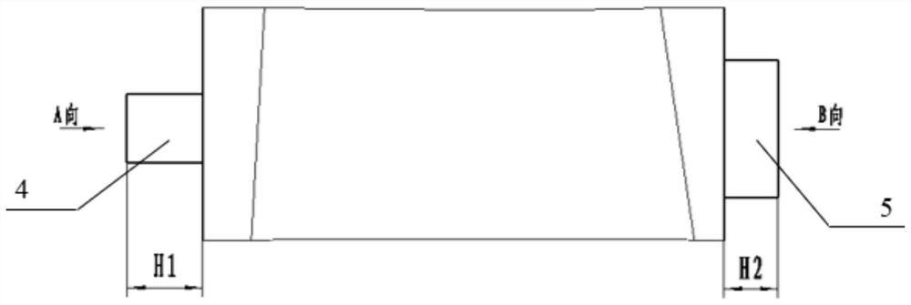
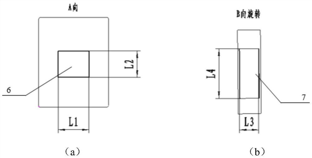
[0038] a. Standardized processing and testing benchmarks: milling at both ends of the blade wool to produce standardized processing benchmarks, such as figure 2 shown. If the machining standards for milling blades with multiple numbers are the same, a set of universal fixtures can be used to process blades with multiple numbers. When testing, the general fixture is used for positioning and the coordinate system is corrected, so no special testing fixture is needed.

[0039] b. Positioning datum with low precision requirement when finishing blade milling: during finishing machining, the machining datum during rough machining can be used for positioning, and the datum accuracy can be set within a wide range.

[0040] c. Non-deformation clamping and positioning method: one end is directly clamped and positioned with a general-purpose fixture for standardized processing benchmarks, and the other end is posit...

Embodiment 3

[0043] a. Standardized processing and testing benchmarks: milling square positioning benchmarks at both ends of the blade, such as figure 2 As shown, all parts of the machined blade are positioned on this basis (except for the reference interference areas at both ends). By standardizing this reference dimension, blades with similar structures and multiple numbers no longer need special fixtures. When testing, the general fixture is used for positioning and the coordinate system is corrected, so no special testing fixture is needed. b. Positioning datum with low precision requirements when finishing milling blades: the disadvantage of fine datum required for traditional finishing of twisted blades. The processing and testing of all parts are carried out based on the theoretical coordinate origin, and the theoretical model is closely combined with the actual processing and testing. The processing size of the blade is no longer directly related to the accuracy of the fixture, t...


PUM


Abstract

The invention discloses a machining process of an aero-engine blade, and belongs to the field of machining and manufacturing of aero-engine blades. The problem that a special clamp is needed for traditional blade machining is solved by adopting a standardized machining reference. The standardized machining reference is adopted for positioning when the blade size is detected in a three-coordinate mode, meanwhile, a coordinate system correction step is added, and the problem that a special positioning measuring tool is needed for three-coordinate detection is solved; and the machining reference is no longer used as a detection reference, and dimensional deviation caused by clamping errors, clamp errors and reference conversion errors can be eliminated. By adopting the machining process to mill a blade, the defects of a traditional milling mode can be well overcome, the process route is simplified, the machining mode that a special clamp, a special measuring tool and a high-precision positioning reference are needed in traditional finish machining is abandoned, finish machining can be carried out by adopting a rough reference, and on the premise of reducing the machining cost and machining difficulty of the blade, the machining precision of the blade is improved.

Description

technical field [0001] The invention belongs to the field of processing and manufacturing of aeroengine blades, and relates to a processing technology of aeroengine blades. Background technique [0002] Aeroengine blades are complex curved parts with many structural features, high dimensional accuracy requirements, and complex and changeable processing techniques. In the traditional processing method, the processing of blades requires special fixtures and special measuring tools, which are expensive and not conducive to storage and management; the finishing of blades requires a high-precision finishing benchmark, which is difficult to process and difficult to guarantee dimensional accuracy; When the blade is finished, the rigidity of the blade body surface is poor, and the processing is easy to deform; if the blade has many complex structures, it needs to go through many times of datum conversion, and the resulting datum conversion error and clamping error accumulation will ...

Claims


Application Information

Patent Timeline
Patent Type & Authority Applications(China)
IPC IPC(8): B23P15/02
CPCB23P15/02
Inventor 全儒振冯帆许立君梁忠效周奋刘虎孟少轩冯磊
Owner AECC AVIATION POWER CO LTD
Learn More