
Robot joint clamping tool, machining equipment and machining method

A technology of robot joints and clamping tooling, which is applied in the direction of metal processing equipment, clamping devices, metal processing machinery parts, etc., and can solve the problems that cannot be processed

Active Publication Date: 2021-09-10
佛山市同泰升精密机电科技有限公司
View PDF9 Cites 0 Cited by
  • Summary
  • Abstract
  • Description
  • Claims
  • Application Information

AI Technical Summary

Problems solved by technology

[0003] The problem in the prior art is that the workpiece clamping mechanism abuts against the outer surface of the workpiece, and the clamped surface of the workpiece cannot be processed, so only the surface of the upper part of the workpiece can be processed

Method used


Image

  • Robot joint clamping tool, machining equipment and machining method
  • Robot joint clamping tool, machining equipment and machining method
  • Robot joint clamping tool, machining equipment and machining method

Examples


Embodiment Construction

[0025] The invention will be described in detail below in conjunction with specific embodiments.

[0026] Such as Figure 3 ~ Figure 6 , is an embodiment of the robot joint clamping tooling of the present invention, specifically:

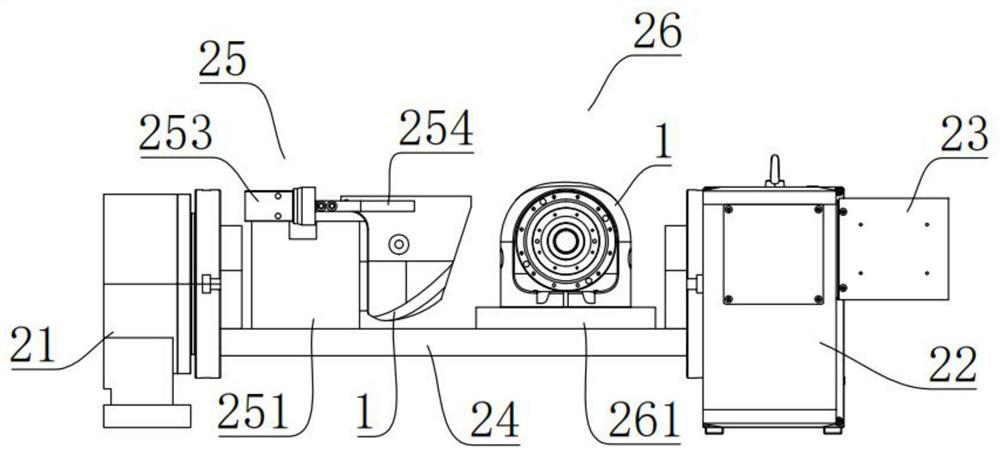
[0027] A robot joint clamping tool 2, comprising a left bearing seat 21, a right bearing seat 22, a main drive mechanism 23, a mounting plate 24, a left clamping assembly 25 and a right clamping assembly 26; the left bearing seat 21 and the right bearing seat 22 Rotatably connected with the left part and the right part of the mounting plate 24 respectively, the left clamping assembly 25 and the right clamping assembly 26 are respectively connected with the left part and the right part of the mounting plate 24, the left clamping assembly 25 and the right clamping assembly 26 For clamping the workpiece, the left clamping assembly 25 is used to clamp the outer side wall of the workpiece, and the right clamping assembly 26 is used to connect the bottom...


PUM


Abstract

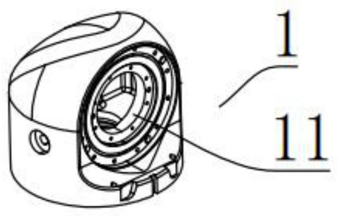
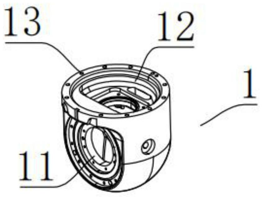
The invention provides a robot joint clamping tool, machining equipment and machining method. The robot joint clamping tool comprises a left bearing seat, a right bearing seat, a main driving mechanism, a mounting plate, a left clamping assembly and a right clamping assembly. The left bearing seat and the right bearing seat are rotatably connected with the left portion and the right portion of the mounting plate correspondingly, the left clamping assembly and the right clamping assembly are connected with the left portion and the right portion of the mounting plate correspondingly and used for clamping a workpiece, the left clamping assembly is used for clamping the outer side wall of the workpiece, and the right clamping assembly is used for being connected with the bottom of the workpiece. The workpiece comprises a blank or a semi-finished product, the blank can be made into the semi-finished product after being subjected to numerical milling, and the semi-finished product can be made into a robot joint after being subjected to numerical milling. The robot joint clamping tool, machining equipment and machining method have the advantage that the inner side wall and the outer side wall of the workpiece can be machined through the same numerical control machine tool.

Description

technical field [0001] The invention belongs to the field of four-axis digital milling, and in particular relates to a robot joint clamping tool, processing equipment and a processing method. Background technique [0002] In order to improve the efficiency of four-axis processing, the four-axis processing tool in the prior art is provided with multiple clamping stations. For example, the Chinese patent with the publication number CN209698531U discloses a four-axis rotary processing tool for the blank of the telescope shell , comprising a rotary drive device arranged on the machine tool guide rail, a rotary frame provided on the rotary drive device, and at least one workpiece clamping mechanism arranged along the direction of the rotation axis, the rotation axis of the rotary frame is parallel to the machine tool guide rail, and The rotary frame rotates along the rotation axis through a rotary drive device; the workpiece clamping mechanism includes a workpiece support plate, ...

Claims


Application Information

Patent Timeline
Patent Type & Authority Applications(China)
IPC IPC(8): B23Q3/00
CPCB23Q3/00B23Q2703/10
Inventor 谢洽伟
Owner 佛山市同泰升精密机电科技有限公司
Learn More