
Lining flange cover and nozzle connection structure

A technology for lining flange covers and connecting structures, which is applied in the direction of flange connections, pipes/pipe joints/fittings, passing components, etc., and can solve problems such as poor stability and reliability, failure of the sealing effect of flange covers, and safety accidents. Achieve the effects of improving stability and reliability, increasing the scope of use, and ensuring welding quality

Active Publication Date: 2022-05-10
CHINA ERZHONG GRP DEYANG HEAVY IND
View PDF18 Cites 0 Cited by
  • Summary
  • Abstract
  • Description
  • Claims
  • Application Information

AI Technical Summary

Problems solved by technology

However, since the screws are arranged on the sealing surface side of the clad liner, in order to prevent the medium from entering the screw hole and corroding the base flange cover, the installation position of the screw can only be located outside the seal surface of the clad liner and close to the clad liner The position of the edge; this causes only the edge of the composite liner to be connected to the base flange cover, while the middle of the composite liner is not connected to the base flange cover, thus making the connection between the composite liner and the base flange cover poor stability and reliability
Especially when the working environment in the reactor is under normal pressure or slightly negative pressure, the lining flange cover with this structure is very easy to cause the middle bulge of the multilayer liner and cause the sealing effect of the flange cover to fail. It will cause the leakage of the medium in the reactor and cause a safety accident

Method used


Image

  • Lining flange cover and nozzle connection structure
  • Lining flange cover and nozzle connection structure
  • Lining flange cover and nozzle connection structure

Examples

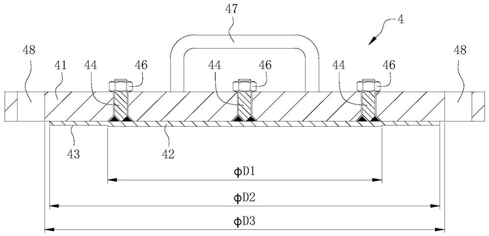
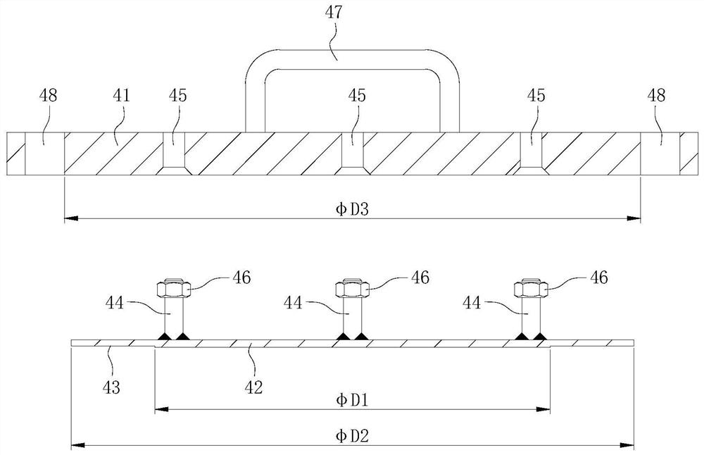
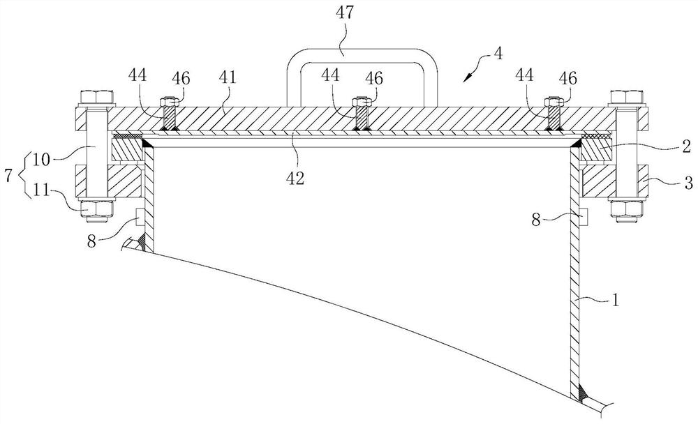

Embodiment Construction

[0024] In order to make those skilled in the art better understand the present invention, the present invention will be further described below in conjunction with the accompanying drawings and embodiments. Apparently, the described embodiments are only some of the embodiments of the present invention, but not all of them. In the case of no conflict, the embodiments and the features in the embodiments of the present invention can be combined with each other.

[0025] figure 1 It is a structural schematic diagram of the lining flange cover provided by the embodiment of the present invention; figure 2 It is an exploded view of the lining flange cover provided by the embodiment of the present invention.

[0026] see figure 1 , figure 2 , the lining flange cover provided by the embodiment of the present invention includes a base flange cover 41 and a composite liner 42; a first sealing surface 43 is provided on the first surface of the composite liner 42; the composite liner...


PUM


Abstract

The invention relates to the technical field of flange covers, and provides a liner flange cover, which includes a base flange cover and a cladding liner; the second surface of the clad liner is bonded to the inner surface of the base flange cover; the cladding The second surface of the liner is welded with several threaded shafts extending toward the base flange cover; the position corresponding to each thread shaft is provided with a first through hole on the base flange cover; A through hole is passed through, and the end of the threaded shaft is threadedly connected with a fixing nut. By welding the threaded shafts on the second surface of the clad liner, the number and installation position of the threaded shafts are not limited by the position of the sealing surface of the clad liner, which improves the reliability of the connection between the clad liner and the basic flange cover stability and reliability. A nozzle connection structure is provided. By setting a lining flange cover with high stability and reliability, the reliability of the sealing performance of the nozzle connection structure is improved, and the application range of the nozzle connection structure is further improved.

Description

technical field [0001] The invention relates to the technical field of flange covers, in particular to a lining flange cover and a nozzle connection structure. Background technique [0002] The reactor is a common comprehensive reaction vessel in the petrochemical industry. The medium in some reactors is highly corrosive, and the reactor needs to be made of titanium with strong corrosion resistance. During the normal working process of the reactor, for non-process nozzles such as manholes, inspection ports, and spare ports on the reactor, flange covers need to be installed at the nozzles. [0003] The traditional flange cover is all made of titanium, although it can meet the requirements of corrosion resistance, but it has the disadvantage of high material cost. In order to reduce the material cost of the flange cover, the lining flange cover composed of stainless steel base layer and titanium clad layer is currently used instead of the full titanium flange cover, but the p...

Claims


Application Information

Patent Timeline
Patent Type & Authority Patents(China)
IPC IPC(8): F16L23/032F16L23/036F16L23/16
CPCF16L23/032F16L23/036F16L23/16
Inventor 袁柳朱永有陈健王志峰伍云
Owner CHINA ERZHONG GRP DEYANG HEAVY IND
Learn More