
Securing of stator segments

A technology of stator segments and stators, applied in threaded fasteners, thin plate connections, electromechanical devices, etc., can solve problems such as complexity

Pending Publication Date: 2021-09-10
FLENDER GMBH
View PDF0 Cites 0 Cited by
  • Summary
  • Abstract
  • Description
  • Claims
  • Application Information

AI Technical Summary

Problems solved by technology

This requires a high degree of complexity and is highly cost-intensive

Method used


Image

  • Securing of stator segments
  • Securing of stator segments
  • Securing of stator segments

Examples


Embodiment Construction

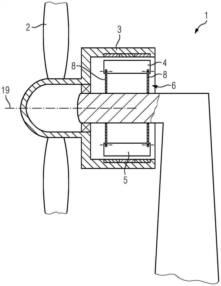
[0037] figure 1 A schematic diagram of a wind power plant 1 with a direct-drive wind generator with an external rotor is shown. The rotor 3 here has permanent magnets, which are not shown in more detail and which interact electromagnetically with the coil system of the stator 4 (the coil system is not shown in more detail), and are rotated around the axis 19 by the turbine 2 of the wind power plant 1 rotation, thus providing electrical energy. When viewed in the circumferential direction, the stator 4 is subdivided into stator segments 5 which are supported in each case on a stator support 6 which has two flanges 8 extending in parallel.

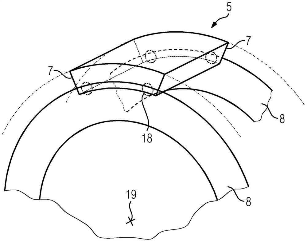
[0038] Such as figure 2 In this illustration, the stator segment 5 is fastened to the stator support 6 by means of suitable fastening means by means of four fastening points 18 , which will be described in more detail.

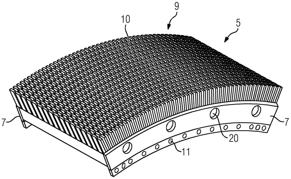
[0039] The stator segment 5 has a laminated core 9 with axially parallel grooves 10 in which a coil system (not descri...


PUM


Abstract

The invention relates to a stator (4) of a direct-drive wind turbine generator, comprising stator segments (5) arranged around the circumference, each segment being positioned, in particular, on two parallel flanges (8) of a common stator support (6), wherein: the flanges (8) of the stator support (6) have bores (12); each stator segment (5) is secured to the flanges (8) by at least two securing devices (18); the stator segment (5) has a segment support (7) providing cavities (11), into which a bore part (17) can be introduced; a securing device (18) has a bore part (17), an alignment pin (13), and at least one shim (15); and the stator segment (5) can be positioned and secured by means of the bore part (17) located in the cavity (11), the alignment pin (13) introduced into the bore (12) of the stator support (6), and the shim (15).

Description

technical field [0001] The invention relates to a stator of a direct-drive wind power plant and a method for assembling and positioning stator segments of such a wind power plant. Background technique [0002] Since the diameter of the stator of the direct-drive wind power generator is greater than or equal to 4 meters, the stator is assembled from a plurality of stator segments viewed from the circumferential direction. The latter are usually six, eight or twelve stator segments assembled to form a ring. Stator segments are usually fixed at both axial ends. Due to the dimensions of the stator, it is difficult to achieve the required tolerances. The production of stator segments and stator supports requires precise fabrication. A flexible adjustment of the mutual position, in particular the radial position, of the stator segments and stator supports is not possible. Therefore, the final outer diameter depends on the exact fabrication of the stator support and stator segm...

Claims


Application Information

Patent Timeline
IPC IPC(8): H02K1/18H02K7/18F16B35/00H02K1/14F16B5/02
CPCH02K1/187H02K7/1838F16B35/005H02K1/148F16B5/0225H02K2201/03Y02E10/72F16B5/02
Inventor A·科泽吉A·林德迈尔D·拉齐斯贝格尔F·X·M·朔贝尔C·施瓦茨鲍尔L·岳
Owner FLENDER GMBH
Features
  • Generate Ideas
  • Intellectual Property
  • Life Sciences
  • Materials
  • Tech Scout
  • Unparalleled Data Quality
  • Higher Quality Content
  • 60% Fewer Hallucinations
Learn More