A self-propelled edible mushroom micro-spray humidifier
An edible fungus and humidifier technology, applied in application, horticulture, agriculture, etc., can solve the problems of uneven upper and lower humidity, different growth rates of edible fungi, poor adaptability, etc.
- Summary
- Abstract
- Description
- Claims
- Application Information
AI Technical Summary
Problems solved by technology
Method used
Image
Examples
Embodiment 1
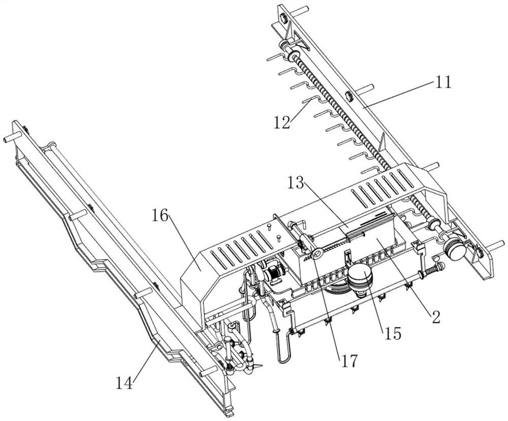
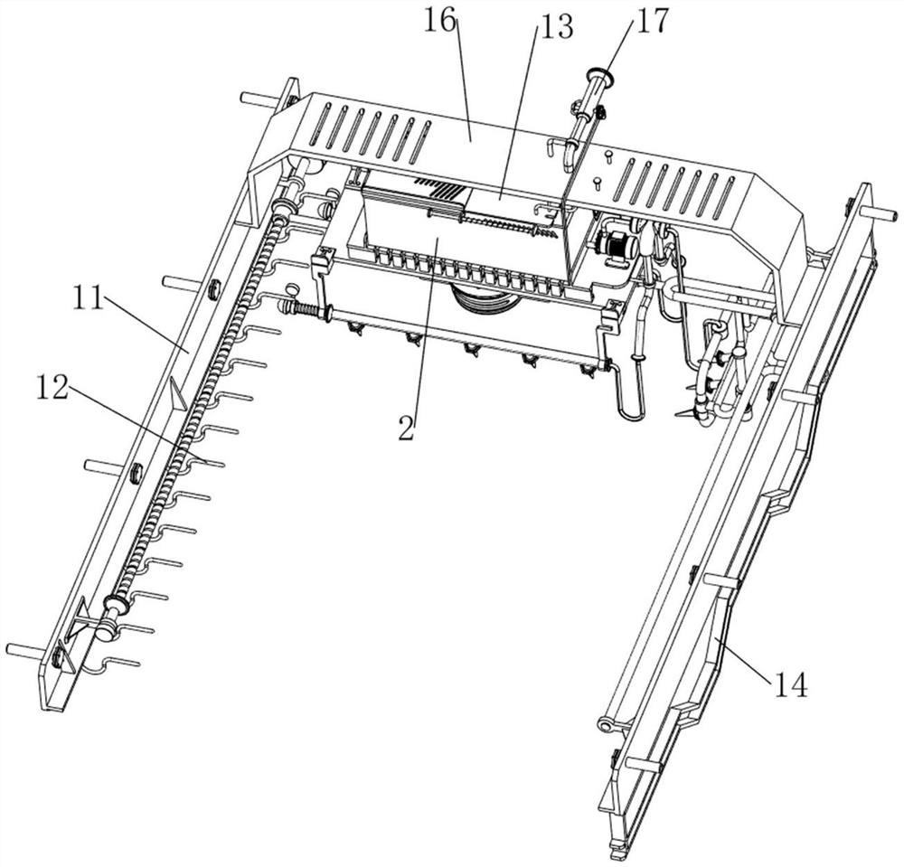
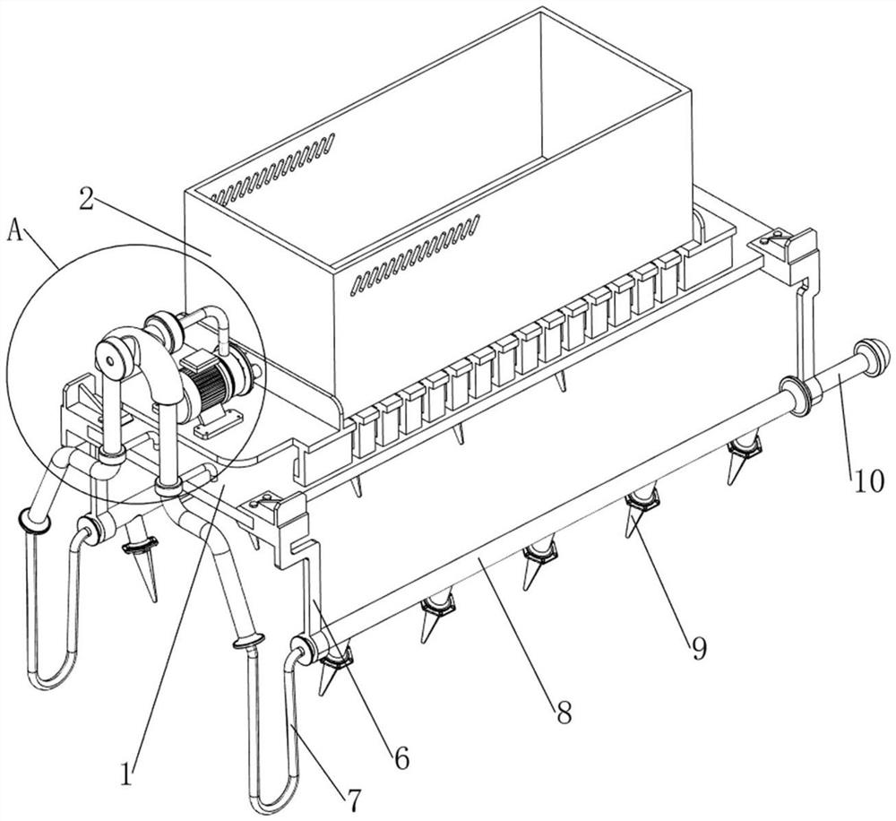
[0037] A self-propelled edible mushroom micro-spray humidifier, such as Figure 1-4 As shown, it includes a bottom plate 1, a water tank 2, a water pump 3, a guide pipe 4, a first fixed column 5, a second fixed column 6, a first hose 7, a first water delivery pipe 8, a first mist spray head 9, The rotating rod 10, the moving mechanism 11 and the steering mechanism 12, the top of the bottom plate 1 is provided with a water tank 2, the left side of the top of the bottom plate 1 is provided with a water pump 3, the right side of the water pump 3 is connected to the water tank 2, and the top left side of the bottom plate 1 is provided with a front-to-back symmetrical A fixed column 5, the first fixed column 5 is located on the lower side of the water pump 3, a guide pipe 4 is connected between the two first fixed columns 5, the upper side of the guide pipe 4 is communicated with the water pump 3, and the front and rear sides of the bottom plate 1 are The second fixed column 6 is s...
Embodiment 2
[0040] On the basis of Example 1, as Figure 1-2 and Figure 5-7 As shown, the moving mechanism 11 includes a mounting plate 111 , a third fixing column 112 , a fourth fixing column 113 , a first motor 114 , a screw rod 115 , a first sliding block 116 , a second sliding block 117 and a first sliding rod 118 , a first slider 116 is arranged in the middle of the bottom right side of the bottom plate 1, a screw rod 115 is rotatably arranged on the first slider 116, a second slider 117 is arranged in the middle of the bottom left side of the bottom plate 1, and the second slider 117 slides on There is a first sliding rod 118, the screw rod 115 and the first sliding rod 118 are connected with a third fixing column 112 on the front and rear sides, and a mounting plate 111 is connected between the third fixing columns 112 on the front and rear sides. A fourth fixing column 113 is arranged on the front side of the inner wall of the mounting plate 111 , and a first motor 114 is arrang...
Embodiment 3
[0045] On the basis of Example 2, as Figure 1-2 and Figure 8-17 As shown, it also includes a cover mechanism 13, the cover mechanism 13 includes a first cover plate 131, a second cover plate 132 and a pull rod 133, the top right side of the water tank 2 is provided with a first cover plate 131, the first cover plate 131 A second cover plate 132 is provided in the upper sliding type, and a pull rod 133 is provided on the left side of the top of the second cover plate 132 .
[0046] When the user needs to fill the water tank 2 with water, the second cover plate 132 can be pulled to the right through the pull rod 133, and then the water tank 2 can be filled with water. That is, in this way, floating objects in the air can be prevented from falling into the water tank 2 .
[0047] It also includes a side spray mechanism 14. The side spray mechanism 14 includes a limit plate 141, a fifth fixed column 142, a connecting rod 143, a first linear spring 144, a second water delivery ...
PUM
 Abstract
Description
Claims
Application Information
 - R&D
- Intellectual Property
- Life Sciences
- Materials
- Tech Scout
- Unparalleled Data Quality
- Higher Quality Content
- 60% Fewer Hallucinations
Browse by: Latest US Patents, China's latest patents, Technical Efficacy Thesaurus, Application Domain, Technology Topic, Popular Technical Reports.
© 2025 PatSnap. All rights reserved.Legal|Privacy policy|Modern Slavery Act Transparency Statement|Sitemap|About US| Contact US: help@patsnap.com


