Material mixing equipment for far infrared ceramic manufacturing
A far-infrared ceramic and material mixing technology, applied in clay preparation devices, unloading devices, chemical instruments and methods, etc., can solve the problem of uneven mixing and achieve the effect of saving manpower
- Summary
- Abstract
- Description
- Claims
- Application Information
AI Technical Summary
Problems solved by technology
Method used
Image
Examples
Embodiment 1
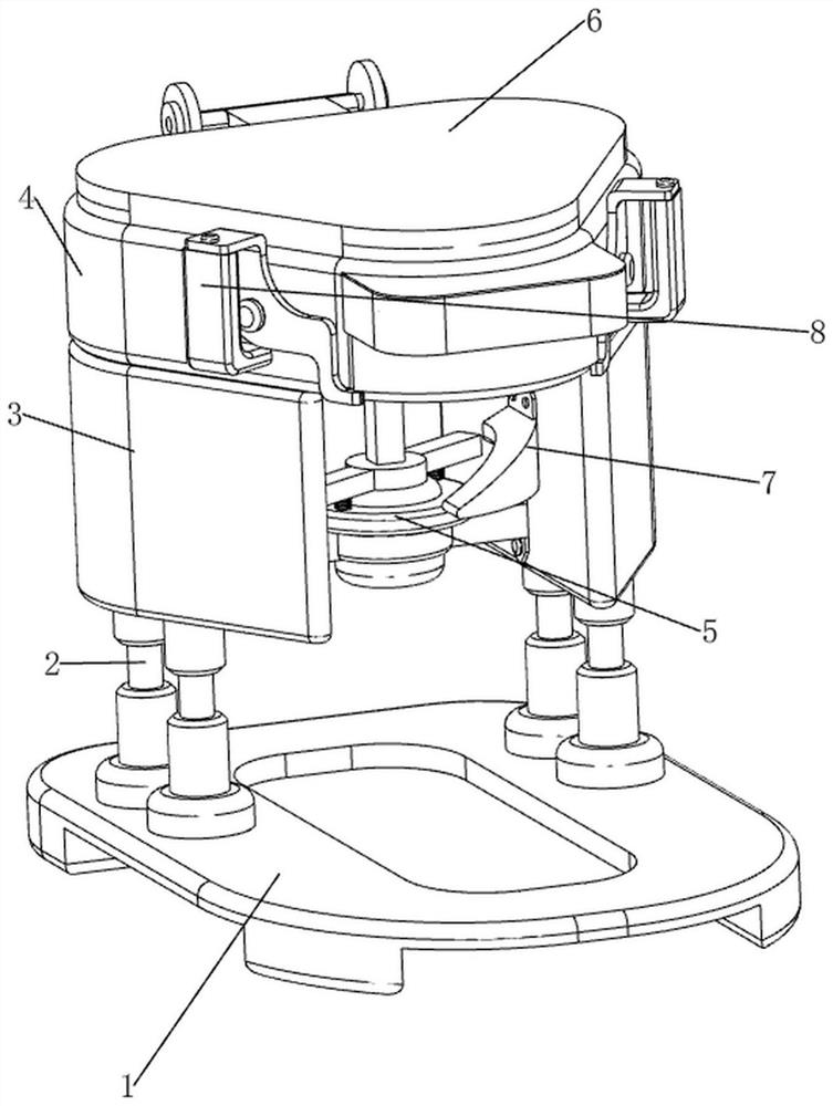
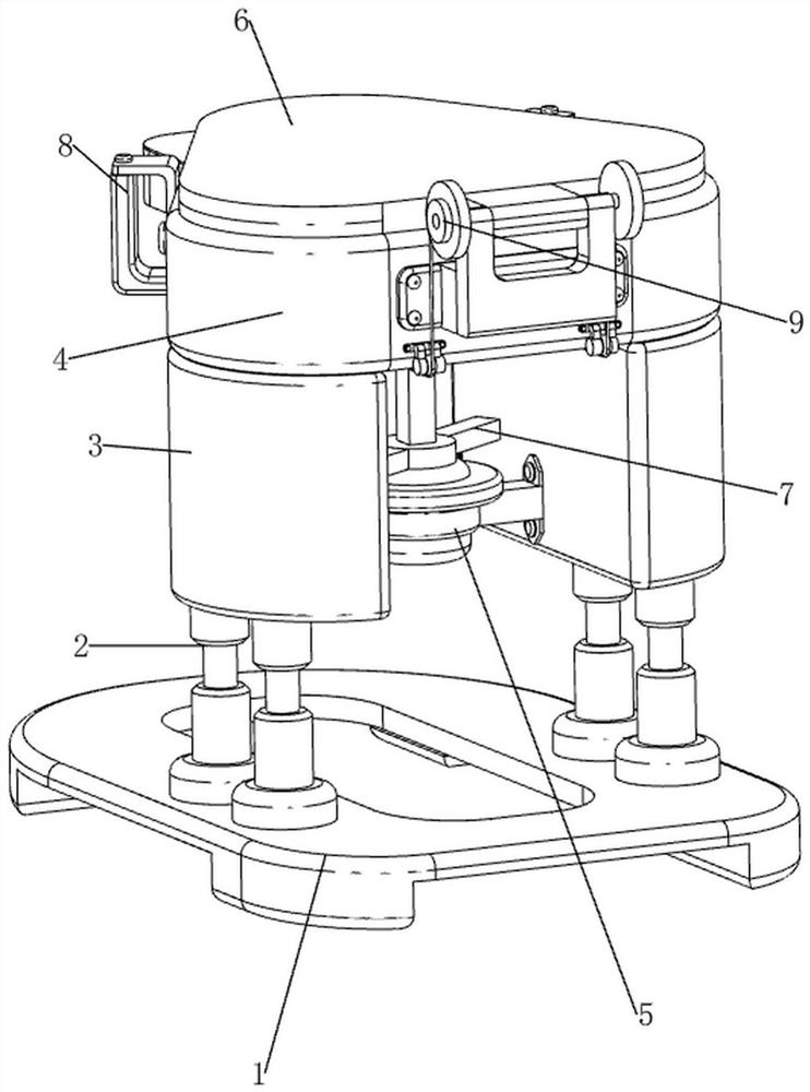
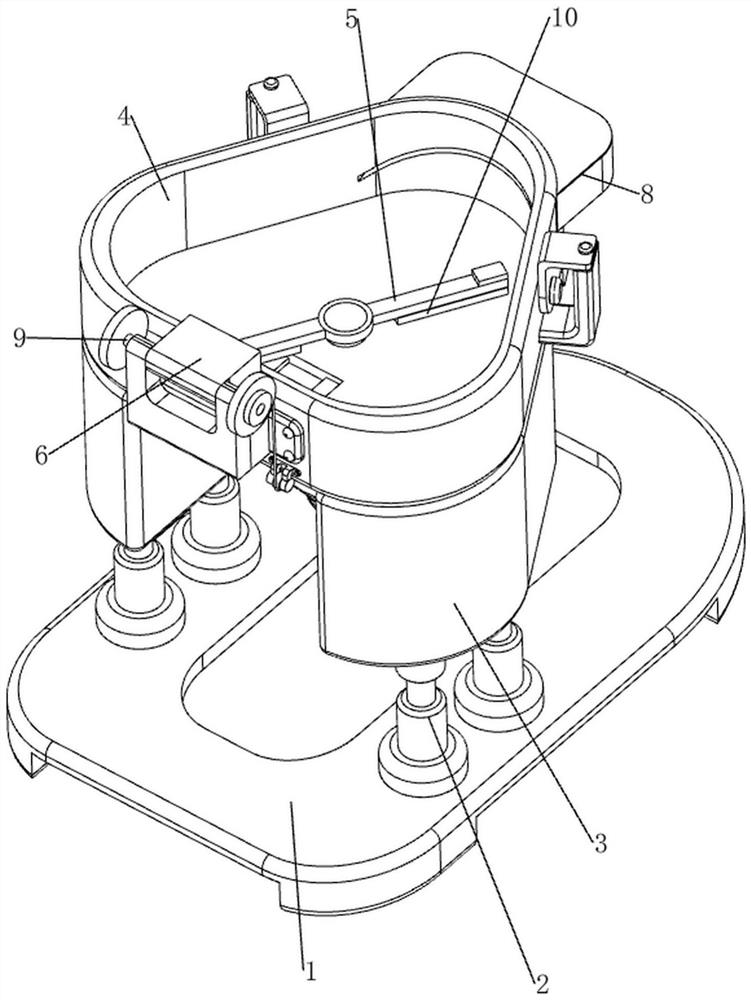
[0071]A kind of material mixing equipment for far-infrared ceramics production, now refer to Figure 1-3 , including a bottom plate 1, a support rod 2, a support block 3, a mixing cylinder 4, a mixing mechanism 5 and a cover mechanism 6, two support rods 2 are welded on the left and right sides of the upper part of the bottom plate 1, and there are four support rods 2, on the same side A support block 3 is welded between the upper sides of the two support rods 2, and a mixing cylinder 4 is connected between the upper sides of the two support blocks 3. A mixing mechanism 5 is connected between the material tank, the mixing cylinder 4 and the two support blocks 3 , and the mixing cylinder 4 is provided with a cover mechanism 6 .
[0072] now refer to figure 1 , figure 2 , image 3 , Figure 4 , Figure 5 , Figure 7 , Figure 12 , Figure 13 with Figure 14 , the mixing mechanism 5 includes a first mounting frame 51, a reduction motor 52, a first rotating shaft 53, a s...
Embodiment 2
[0076] On the basis of embodiment 1, now refer to figure 1 , figure 2 with Figure 7 , also includes up and down moving mechanism 7, and up and down moving mechanism 7 includes rotating ring 71, ejector rod 73, elastic assembly 72 and wedge-shaped block 74, is provided with rotating ring 71 on the reduction motor 52, and rotating ring 71 top left and right sides Elastic assembly 72 is all provided, and elastic assembly 72 is made up of telescopic rod and spring, and rotating ring 71 top, left and right sides are all provided with telescopic rod, is welded with ejector rod 73 between two telescopic rod upper sides, and ejector rod 73 and square shaft 55 connection, the push rod 73 is slidably connected with the first rotating shaft 53, a spring is connected between the left and right sides of the bottom of the push rod 73 and the rotating ring 71, the spring is wound on the telescopic rod, and the left part of the support block 3 on the right is passed through the bolt A wed...
PUM
 Abstract
Description
Claims
Application Information
 - R&D
- Intellectual Property
- Life Sciences
- Materials
- Tech Scout
- Unparalleled Data Quality
- Higher Quality Content
- 60% Fewer Hallucinations
Browse by: Latest US Patents, China's latest patents, Technical Efficacy Thesaurus, Application Domain, Technology Topic, Popular Technical Reports.
© 2025 PatSnap. All rights reserved.Legal|Privacy policy|Modern Slavery Act Transparency Statement|Sitemap|About US| Contact US: help@patsnap.com


