Power adjusting circuit, power adjusting method and electric chafing dish

A power adjustment and circuit technology, which is applied to cooking utensils, timing control ignition mechanisms, heating devices, etc., can solve the problems of burning food and adjusting heating power

Pending Publication Date: 2021-09-14
BEAR ELECTRICAL APPLIANCE CO LTD +1
View PDF5 Cites 5 Cited by
  • Summary
  • Abstract
  • Description
  • Claims
  • Application Information

AI Technical Summary

Problems solved by technology

However, it has been found in practice that the heating power of the mechanical temperature control method is constant throughout the heating process. When the electric hot pot is used for grilling or cooking, the constant heating power can easily cause the ingredients to burn, and it is difficult to automatically adjust the heating according to the current temperature of the electric hot pot. power

Method used


Image

  • Power adjusting circuit, power adjusting method and electric chafing dish
  • Power adjusting circuit, power adjusting method and electric chafing dish
  • Power adjusting circuit, power adjusting method and electric chafing dish

Examples


Embodiment 1

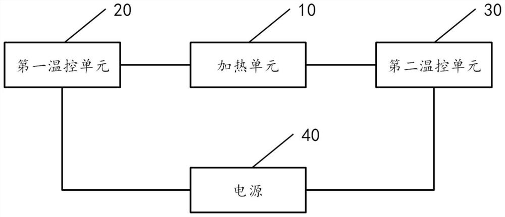
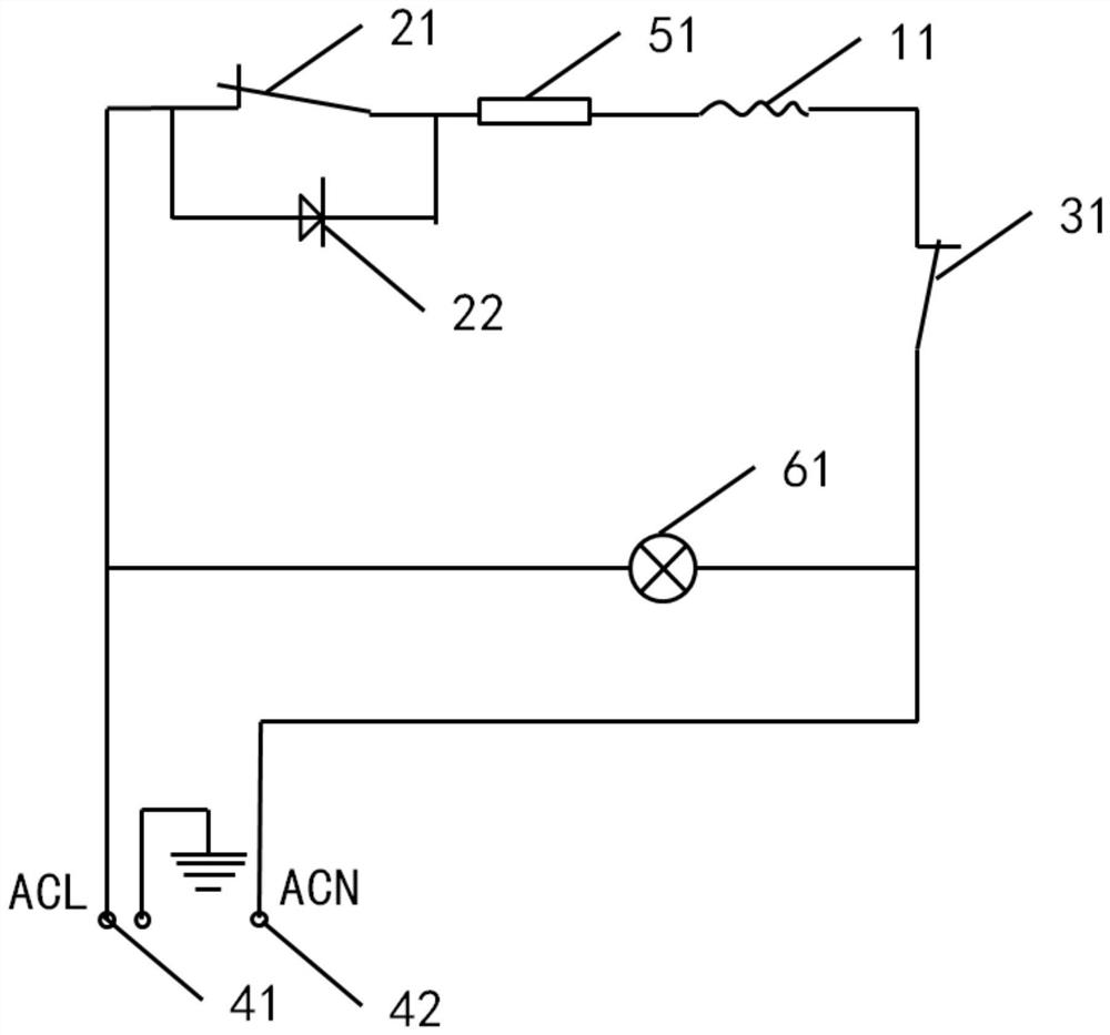
[0056] see figure 1 and image 3 , figure 1 It is a block diagram of a power adjustment circuit disclosed in an embodiment of the present invention, image 3 It is a power adjustment circuit diagram disclosed by the embodiment of the present invention. like figure 1 and image 3 As shown, the power regulation circuit may include:

[0057] The heating unit 10, the first temperature control unit 20 and the second temperature control unit 30, one end of the heating unit 10 is electrically connected to one end of the first temperature control unit 20, and the other end of the heating unit 10 is electrically connected to one end of the second temperature control unit 30 , the other end of the first temperature control unit 20 is used to electrically connect the first pole 41 of the power supply 40, and the other end of the second temperature control unit 30 is used to electrically connect the second pole 42 of the power supply 40;

[0058] Wherein, the heating unit 10 include...

Embodiment 2

[0084] see Figure 4 , Figure 4 It is a flow chart of a power adjustment method disclosed by an embodiment of the present invention. like Figure 4 As shown, the power adjustment method may include the following operations:

[0085] 101. Adjust the adjustable temperature controller 31 so that the heating element 11 is heated with the first power.

[0086] In the embodiment of the present invention, the adjustable temperature controller 31 has at least one gear. For example, the gears are divided into three gears: high gear, middle gear and low gear. The adjustable temperature controller 31 can be in the high gear , switch between the middle gear and the low gear, it should be noted that, when the adjustable temperature controller 31 is respectively adjusted to the high gear, the middle gear and the low gear, the heating element 11 is heated with the first power.

[0087] In the embodiment of the present invention, the first power is the maximum full power. When the heatin...

Embodiment 3

[0095] see Figure 5 , Figure 5 It is a flow chart of a power adjustment method disclosed by an embodiment of the present invention. like Figure 5 As shown, the power adjustment method may include the following operations:

[0096] 201. Adjust the adjustable temperature controller 31, so that the heating element 11 is heated with the first power.

[0097] 202. Determine whether the temperature of the heating element 11 is greater than or equal to the first trigger temperature. When the judgment result of step 202 is yes, trigger the execution of step 203; when the judgment result of step 202 is no, trigger the execution of step 204.

[0098] 203. Control the kick thermostat 21 to switch from the on state to the off state, so that the heating power of the heating element 11 is switched from the first power to the second power, wherein the first power is greater than the second power.

[0099] 204. Control the kick thermostat to keep in a conducting state, so that the heat...


PUM


Abstract

The invention provides a power adjusting circuit, a power adjusting method and an electric chafing dish. The circuit comprises a heating unit, a first temperature control unit and a second temperature control unit, one end of the heating unit is electrically connected with one end of the first temperature control unit, the other end of the heating unit is electrically connected with one end of the second temperature control unit, the other end of the first temperature control unit is electrically connected with a first pole of a power supply, and the other end of the second temperature control unit is electrically connected with a second pole of the power supply; the heating unit comprises a heating element used for providing heat for an electric appliance; and the first temperature control unit comprises a kick temperature controller and a diode which are connected in parallel, the trigger temperature of the kick temperature controller is a first trigger temperature, when the temperature of the heating element is greater than or equal to the first trigger temperature, the kick temperature controller is disconnected, the heating power of the heating element is switched from a first power to a second power, and the first power is greater than the second power. Therefore, the power adjusting circuit can automatically adjust the heating power according to the current temperature condition, so that the food materials are prevented from being burnt.

Description

technical field [0001] The invention relates to the technical field of kitchen appliances, in particular to a power adjustment circuit, a power adjustment method and an electric hot pot. Background technique [0002] With the rapid development of kitchen appliance technology, electric hot pots have more and more functions, which can realize functions such as boiling water, cooking, and barbecue. Multifunctional electric hot pots greatly facilitate people's lives and improve the quality of life. [0003] At present, most multifunctional electric hot pots use a mechanical temperature control method to adjust the temperature, that is, when the temperature inside the electric hot pot is higher than the preset temperature, the heating element is disconnected to stop heating; when the temperature inside the electric hot pot is lower than the preset temperature , Turn on the heating element for heating, so that the temperature in the electric hot pot is controlled within the range ...

Claims


Application Information

Patent Timeline
Patent Type & Authority Applications(China)
IPC IPC(8): A47J36/32A47J36/24
CPCA47J36/32A47J36/2483
Inventor 邓财科罗峥
Owner BEAR ELECTRICAL APPLIANCE CO LTD
Why Eureka
Try Eureka