Manufacturing machine for square rubber cushion block for cabinet

A rubber pad, square technology, applied in the direction of metal processing, etc., can solve the problems of affecting production progress, slow operation speed, labor-intensive, etc.

Inactive Publication Date: 2021-09-14
李雪萍
View PDF0 Cites 4 Cited by
  • Summary
  • Abstract
  • Description
  • Claims
  • Application Information

AI Technical Summary

Problems solved by technology

[0002] Rubber pads are widely used, and the shapes of rubber pads are various, such as rectangle, square and polygon, etc., so that when people make rubber pads, they need to cut rubber pads into different shapes, and square rubber pads are relatively speaking. It is used a lot, so cutting the rubber pads with cutting tools now requires manual fixing and limiting of the rubber pads, and then cutting with the cutting tools. This slows down the operation and affects the production progress. Manual operation is labor-intensive. This will lead to an increase in the cost of the factory

Method used


Image

  • Manufacturing machine for square rubber cushion block for cabinet
  • Manufacturing machine for square rubber cushion block for cabinet
  • Manufacturing machine for square rubber cushion block for cabinet

Examples


Embodiment 1

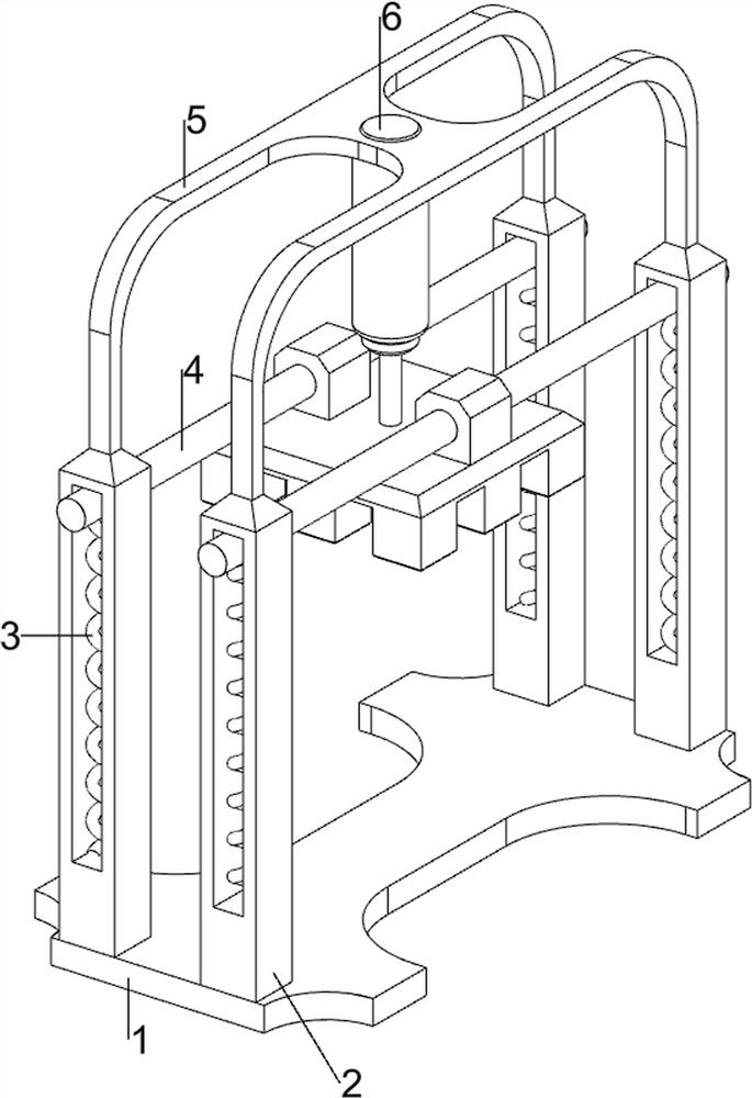
[0027] A machine for manufacturing square rubber pads for cabinets, such as Figure 1-4 As shown, it includes a bottom plate 1, a first slide rail 2, a first spring 3, a cutter 4, a placement frame 5, a cylinder 6, a placement mechanism 7 and an anti-jamming mechanism 8, and the bottom plate 1 is provided with first slide rails on four sides. 2. A placement frame 5 is connected between the tops of the first slide rails 2, a cutter 4 is slidably connected between the first slide rails 2, and the four sides of the bottom of the cutter 4 are arranged between the first slide rail 2 on the same side. There is a first spring 3, a cylinder 6 is arranged in the middle of the placement frame 5, the bottom of the cylinder 6 is connected with the cutter 4, a placement mechanism 7 is arranged on the bottom plate 1, and an anti-jamming mechanism 8 is connected between the first slide rails 2 .

[0028] Placement mechanism 7 includes support feet 70, mounting plate 71, rotating shaft 72, sp...

Embodiment 2

[0032] On the basis of Example 1, such as Figure 5-8 As shown, it also includes a limit mechanism 9, and the limit mechanism 9 includes a fixed frame 90, a first telescopic rod 91, a placement block 92, a moving plate 93, a fixed rod 94, a limit plate 95, a second spring 96 and a third spring. Spring 97, cutter 4 left and right sides and front side are all provided with two fixed mounts 90, are all provided with first telescopic rod 91 on the fixed mount 90, first telescopic rod 91 insides are all provided with spring, mounting plate 71 left and right sides Two placing blocks 92 are provided on the side and the front side, and the left and right sides and the front side of the mounting plate 71 are slidingly connected to the limiting plate 95, and the both sides of the limiting plate 95 and the placing block 92 on the same side are provided with a second Two springs 96, both sides of the limiting plate 95 are rotatably connected with a fixed rod 94, the fixed rod 94 is provid...


PUM


Abstract

The invention relates to a manufacturing machine, and particularly relates to a manufacturing machine for a square rubber cushion block for a cabinet. The manufacturing machine for the square rubber cushion block for the cabinet can improve the working efficiency and reduce the production cost. According to the technical scheme, the manufacturing machine for the square rubber cushion block for the cabinet comprises a bottom plate, first sliding rails, first springs, a cutter, a placing frame, an air cylinder and a placing mechanism, wherein the first sliding rails are arranged on the four sides of the bottom plate, the placing frame is connected between the tops of the first sliding rails, the cutter is connected between the first sliding rails in a sliding mode, the first springs are arranged between the four sides of the bottom of the cutter and the first sliding rails on the same side, the air cylinder is arranged in the middle of the placing frame, the bottom of the air cylinder is connected with the cutter, and the placing mechanism is arranged on the bottom plate. Through the cooperation between the placing mechanism and an anti-clamping mechanism, materials can be automatically cut, so that the square rubber cushion block is formed.

Description

technical field [0001] The invention relates to a manufacturing machine, in particular to a manufacturing machine for square rubber pads for cabinets. Background technique [0002] Rubber pads are widely used, and the shapes of rubber pads are various, such as rectangle, square and polygon, etc., so that when people make rubber pads, they need to cut rubber pads into different shapes, and square rubber pads are relatively speaking. It is used a lot, so cutting the rubber pads with cutting tools now requires manual fixing and limiting of the rubber pads, and then cutting with the cutting tools. This slows down the operation and affects the production progress. Manual operation is labor-intensive. This leads to an increase in the cost of the factory. [0003] In order to alleviate the above-mentioned problems, a kind of square rubber pad manufacturing machine for cabinets that can improve work efficiency and reduce production cost is now developed. Contents of the invention...

Claims


Application Information

Patent Timeline
Patent Type & Authority Applications(China)
IPC IPC(8): B26D1/09B26D5/12B26D7/01B26D7/02B26D7/32B26D7/18
CPCB26D1/095B26D5/12B26D7/015B26D7/025B26D7/32B26D7/18
Inventor 李雪萍
Owner 李雪萍
Why Eureka
Try Eureka