A stable injection mold for automobile bumper

A technology for automobile bumpers and injection molds, which is applied in the direction of spring/shock absorber, vibration suppression adjustment, non-rotational vibration suppression, etc. It can solve the problems of difficult air discharge from materials, standard deviation of bumpers, and single movement mode. To achieve the effect of increasing the service life, improving the stability of the die, and increasing the form of motion

Active Publication Date: 2022-08-05
JIANGSU YUJIA MACHINERY MFG CO LTD
View PDF1 Cites 0 Cited by
  • Summary
  • Abstract
  • Description
  • Claims
  • Application Information

AI Technical Summary

Problems solved by technology

[0003] Existing injection molds have a single movement mode during work, and the air contained in the material inside the mold is difficult to discharge, resulting in a low uniformity of the material in the mold, and the standard of the bumper produced is poor, which is inconvenient and widely popularized

Method used


Image

  • A stable injection mold for automobile bumper
  • A stable injection mold for automobile bumper
  • A stable injection mold for automobile bumper

Examples


Embodiment 1

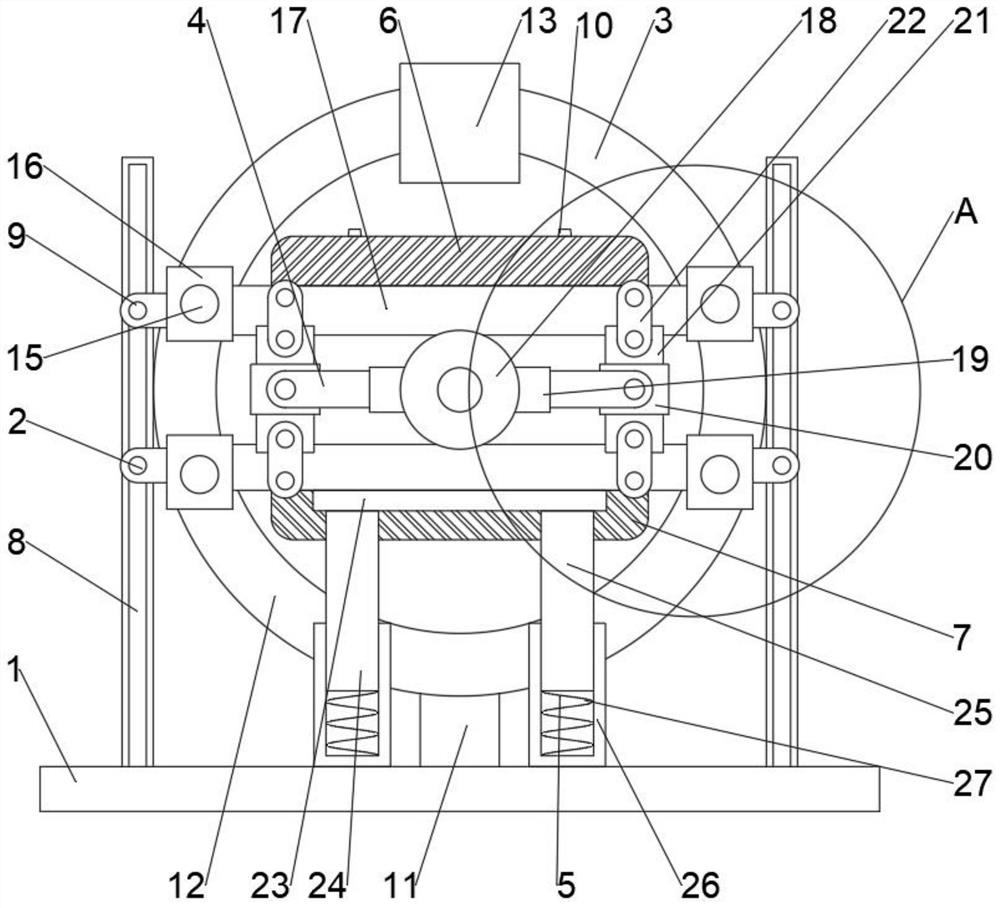
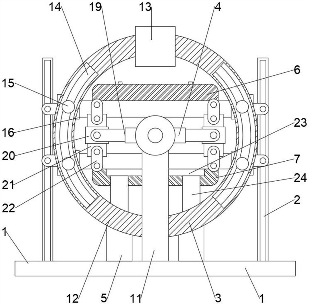
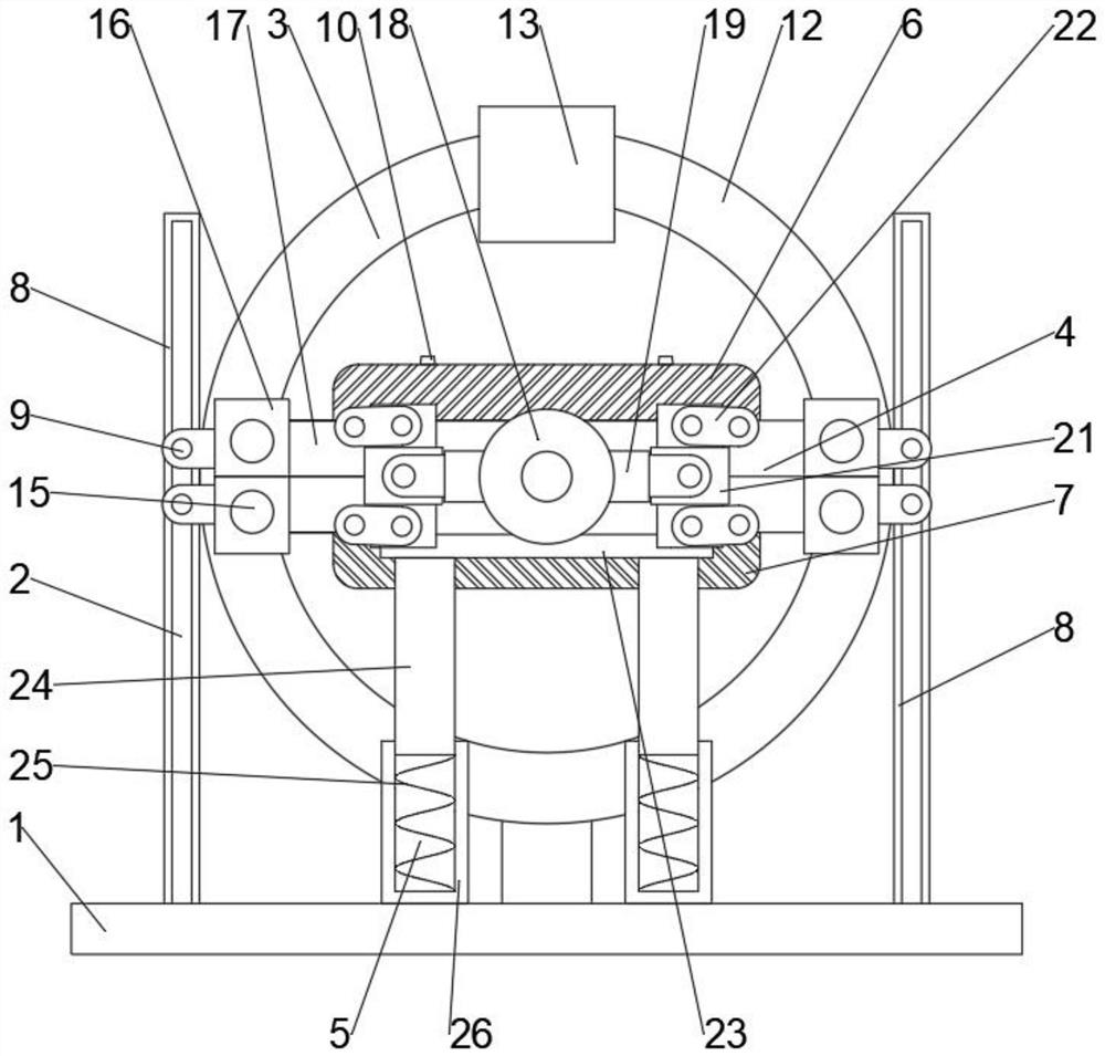
[0025] like Figure 1-5 As shown, a stable injection mold for an automobile bumper proposed by the present invention includes a frame 1, a lifting component 2, a rotating component 3, a die component 4 and a buffer component 5; the lifting component 2, the rotating component 3 and the buffer component 5; 5 is arranged on the frame 1; the die assembly 4 is arranged on the rotating assembly 3; the buffer assembly 5 is located below the die assembly 4; the upper die 6 and the lower die 7 are provided with a ventilation valve 10; Rotating base 11, turntable 12, driving member 13, rotating track 14, sliding base 15 and moving base 16; the rotating base 11 is arranged on the rack 1; the turntable 12 is arranged on the rotating base 11; The sliding seat 15 driven by the driving member 13 is slidably arranged on the rotating track 14; the moving seat 16 is arranged on the sliding seat 15 and is slidably connected with the turntable 12; The telescopic rod 19, the sleeve plate 20, the ...

Embodiment 2

[0029] like Figure 1-5 As shown, the present embodiment proposes a stable injection mold for an automobile bumper. Compared with the first embodiment, the lift assembly 2 includes a lift track 8 and a lift seat 9; the lift track 8 is arranged on the frame 1; the lift seat 9 slides Set on the lift rail 8 .

Embodiment 3

[0031] like Figure 1-5 As shown, the present embodiment proposes a stable injection mold for an automobile bumper. Compared with the first embodiment, the buffer assembly 5 includes a buffer plate 23 and a buffer seat 24; the buffer seat 24 is arranged on the frame 1; the buffer plate 23 is arranged On the buffer seat 24 and below the die plate 17 .

[0032] By setting the buffer assembly 8, the buffer plate 23 and the buffer seat 24 are used to protect the upper die 6 or the lower die 7 from buffering and shock absorption, thereby improving the service life of the components in the present invention and increasing the use times of the upper die 6 and the lower die 7 .


PUM


Abstract

The invention relates to the technical field of molds, in particular to a stable injection mold for an automobile bumper, comprising a frame, a lifting assembly, a rotating assembly, a die assembly and a buffer assembly; the lifting assembly, the rotating assembly and the buffer assembly are arranged on the frame ; The die assembly is arranged on the rotating component; the buffer component is located below the die assembly; the upper die and the lower die are provided with ventilation valves. In the present invention, by arranging a lifting component and a rotating component, the lifting seat is used to drive the mold plate to move up and down on the frame; the movable seat is used to drive the mold plate to rotate on the turntable, thereby increasing the movement form of the mold during the injection molding process and driving the mold to rotate. , which is conducive to improving the uniformity of the material in the mold, thereby improving the production quality of the material; by setting the die assembly, the die stability of the upper die and the lower die on the die plate is improved, and it is convenient to make the upper die and the lower die. In the pressing state, it rotates synchronously with the turntable.

Description

technical field [0001] The invention relates to the technical field of molds, in particular to a stable injection mold for automobile bumpers. Background technique [0002] Injection molding is a method of producing shapes for industrial products. Products usually use rubber injection molding and plastic injection molding. Injection molding can also be divided into injection molding molding method and die casting method; in order to improve production efficiency, automobile bumpers are mostly produced with injection molds. [0003] The existing injection mold has a single movement mode during operation, and the air contained in the material inside the mold is difficult to discharge, resulting in a low uniformity of the material in the mold, and the produced bumper has a poor standard, which is inconvenient and widely popularized. SUMMARY OF THE INVENTION [0004] In order to solve the technical problems existing in the background technology, the present invention propose...

Claims


Application Information

Patent Timeline
Patent Type & Authority Patents(China)
IPC IPC(8): B29C45/26B29C45/34B29C45/17F16F15/04F16F15/067
CPCB29C45/2681B29C45/34B29C45/1742F16F15/067F16F15/04B29C2045/1784
Inventor 顾仁伟倪清玉
Owner JIANGSU YUJIA MACHINERY MFG CO LTD
Why Eureka
Try Eureka