Stable injection mold for automobile bumper

A technology for automobile bumpers and injection molds, which is used in springs/shock absorbers, vibration suppression adjustment, non-rotational vibration suppression, etc., and can solve problems such as inconvenience for widespread promotion, standard deviation of bumpers, and difficulty in discharging air contained in materials.

Active Publication Date: 2021-09-14
JIANGSU YUJIA MACHINERY MFG CO LTD
View PDF1 Cites 0 Cited by
  • Summary
  • Abstract
  • Description
  • Claims
  • Application Information

AI Technical Summary

Problems solved by technology

[0003] Existing injection molds have a single movement mode during work, and the air contained in the material inside the mold is difficult to discharge, resulting in a low uniformity of the material in the mold, and the standard of the bumper produced is poor, which is inconvenient and widely popularized

Method used


Image

  • Stable injection mold for automobile bumper
  • Stable injection mold for automobile bumper
  • Stable injection mold for automobile bumper

Examples


Embodiment 1

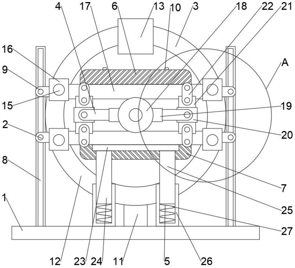
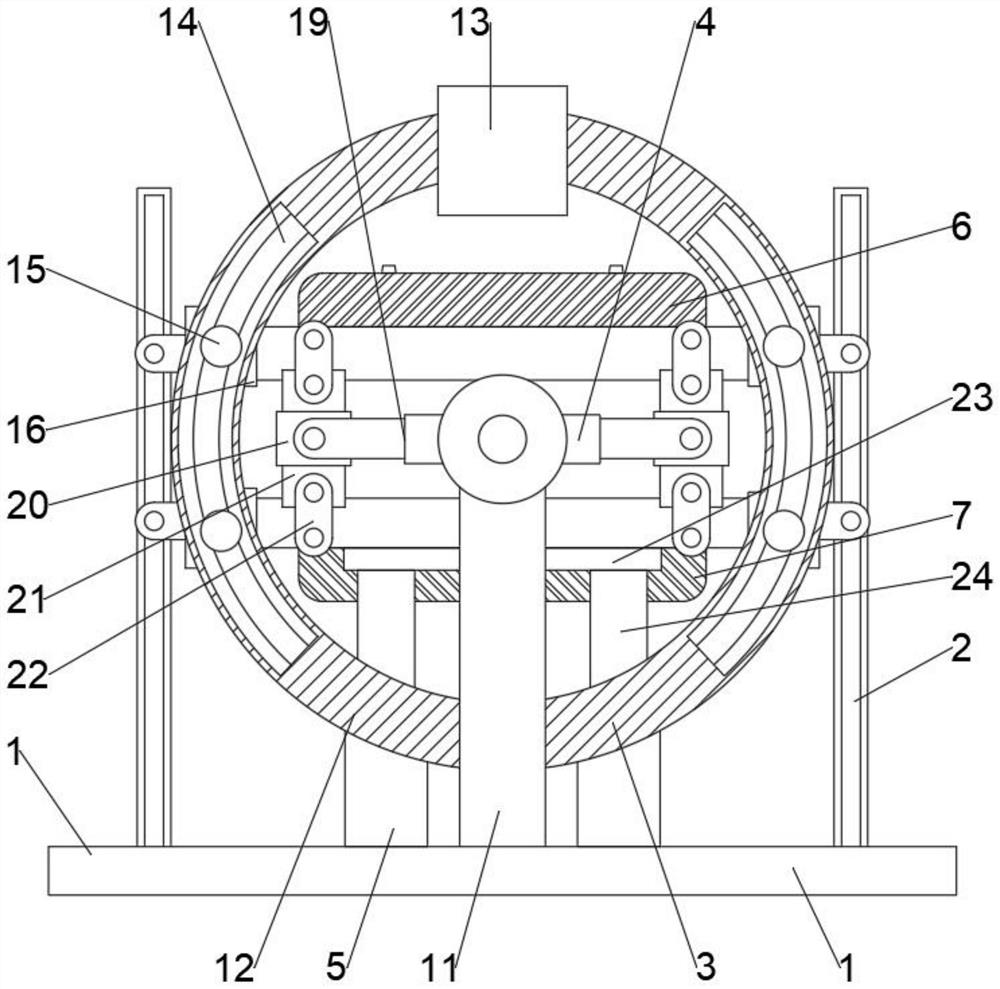
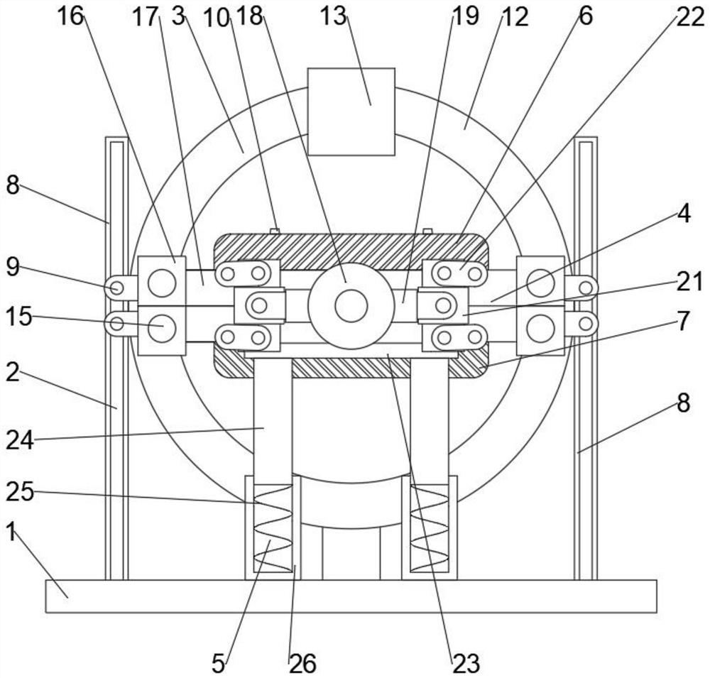
[0025] Such as Figure 1-5 As shown, a stable injection mold for automobile bumper proposed by the present invention includes frame 1, lifting assembly 2, rotating assembly 3, die assembly 4 and buffer assembly 5; lifting assembly 2, rotating assembly 3 and buffer assembly 5 is arranged on the frame 1; the compression mold assembly 4 is arranged on the rotary assembly 3; the buffer assembly 5 is located below the compression mold assembly 4; the upper mold 6 and the lower mold 7 are provided with a vent valve 10; the rotary assembly 3 includes Turning seat 11, rotating disk 12, driver 13, rotating track 14, sliding seat 15 and moving seat 16; Turning seat 11 is arranged on the frame 1; The sliding seat 15 driven by the driver 13 is slidably arranged on the rotating track 14; the moving seat 16 is arranged on the sliding seat 15, and is slidably connected with the turntable 12; Telescopic rod 19, cover plate 20, sliding plate 21 and rotating member 22; Die plate 17 is detachab...

Embodiment 2

[0029] Such as Figure 1-5 As shown, the present embodiment proposes a stable injection mold for automobile bumper. Compared with Embodiment 1, the lifting assembly 2 includes a lifting track 8 and a lifting seat 9; the lifting track 8 is arranged on the frame 1; the lifting seat 9 slides Set on the lifting track 8.

Embodiment 3

[0031] Such as Figure 1-5 As shown, the present embodiment proposes a stable injection mold for automobile bumper. Compared with Embodiment 1, the buffer assembly 5 includes a buffer plate 23 and a buffer seat 24; the buffer seat 24 is arranged on the frame 1; the buffer plate 23 is arranged On the buffer seat 24 and below the mold plate 17 .

[0032] By arranging the buffer assembly 8, the buffer plate 23 and the buffer seat 24 are used to buffer and protect the upper mold 6 or the lower mold 7, thereby improving the service life of the parts in the present invention and increasing the number of times of use of the upper mold 6 and the lower mold 7 .


PUM


Abstract

The invention relates to the technical field of molds, in particular to a stable injection mold for an automobile bumper. The stable injection mold comprises a rack, a lifting assembly, a rotating assembly, a mold pressing assembly and a buffering assembly. The lifting assembly, the rotating assembly and the buffering assembly are arranged on the rack. The mold pressing assembly is arranged on the rotating assembly. The buffering assembly is located below the mold pressing assembly. Ventilation valves are arranged on an upper mold body and a lower mold body. According to the stable injection mold, the lifting assembly and the rotating assembly are arranged, and a lifting base is used for driving a mold plate to ascend and descend on the rack; a movable base is used for driving the mold plate to rotate on a rotating disc, and therefore the motion form of the mold in the injection molding process is increased, the mold is driven to rotate, the uniformity degree of materials in the mold can be improved, and then the production quality of the materials is improved; and the mold pressing assembly is arranged, the mold pressing stability of the upper mold body and the lower mold body on the mold plate is improved, and the upper mold body and the lower mold body can synchronously rotate with the rotating disc in the press fit state.

Description

technical field [0001] The invention relates to the technical field of moulds, in particular to a stable injection mold for automobile bumpers. Background technique [0002] Injection molding is a method of producing shapes for industrial products. Products usually use rubber injection molding and plastic injection molding. Injection molding can also be divided into injection molding molding method and die-casting method; in order to improve production efficiency, automobile bumpers are mostly produced by injection molds. [0003] Existing injection molds have a single movement mode during work, and the air contained in the material inside the mold is difficult to discharge, resulting in a low degree of uniformity of the material in the mold, and the standard of the bumper produced is poor, which is inconvenient and widely popularized. Contents of the invention [0004] In order to solve the technical problems existing in the background technology, the present invention ...

Claims


Application Information

Patent Timeline
Patent Type & Authority Applications(China)
IPC IPC(8): B29C45/26B29C45/34B29C45/17F16F15/04F16F15/067
CPCB29C45/2681B29C45/34B29C45/1742F16F15/067F16F15/04B29C2045/1784
Inventor 顾仁伟倪清玉
Owner JIANGSU YUJIA MACHINERY MFG CO LTD
Why Eureka
Try Eureka