Sand table model with movable house internal structures
A technology of internal structure and sand table, applied in teaching models, instruments, educational appliances, etc., can solve the problems of low installation adaptability, poor simulation display function, etc.
- Summary
- Abstract
- Description
- Claims
- Application Information
AI Technical Summary
Problems solved by technology
Method used
Image
Examples
Embodiment 1
[0048] as attached Figure 4 to attach Figure 5 Shown:
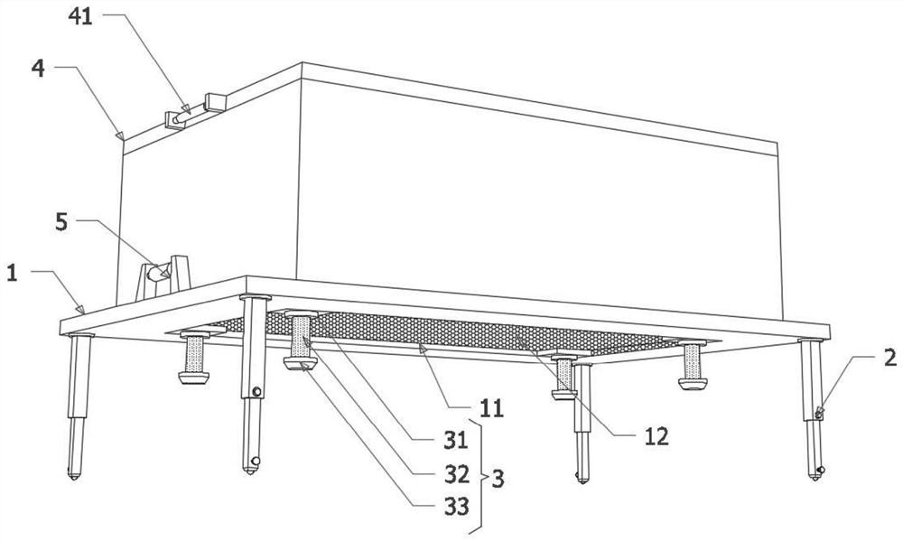
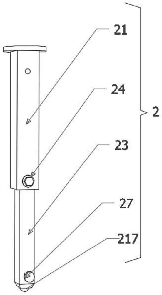
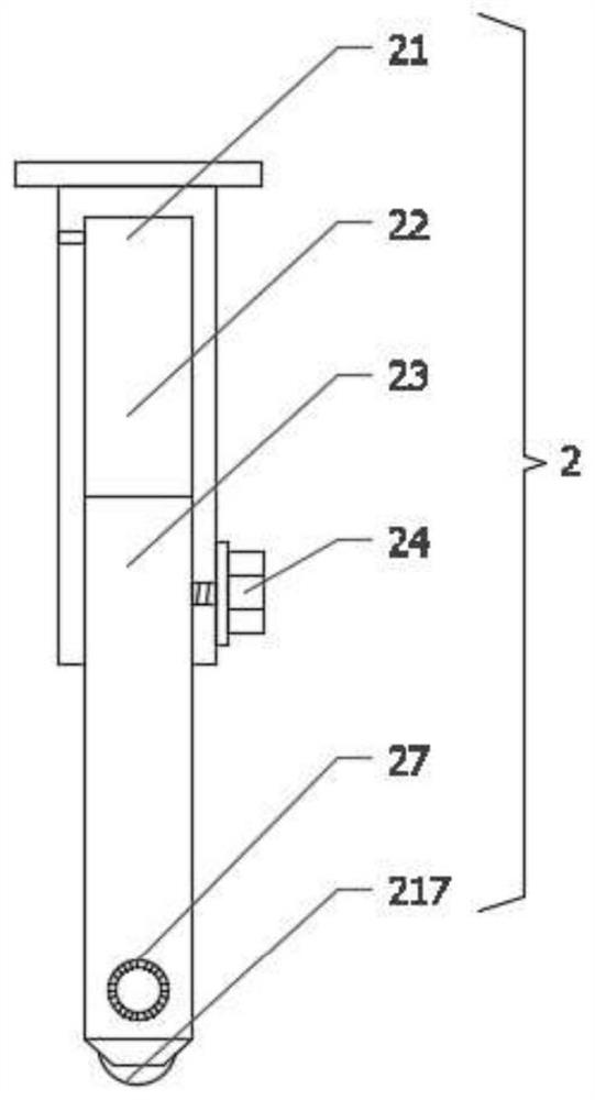
[0049] First of all, the bottom ends of the four supporting shafts 23 are provided with mounting cavities 25, and the lower bottom cavity openings of the four mounting cavities 25 are embedded with rolling balls 217, and the bottom faces of the four square extruding blocks 216 are aligned with the corresponding The rolling ball 217 is compatible with the design, and the rolling ball 217 that can be rotated at multiple angles can be used to adjust the relative insertion depth of the supporting shaft tube 21 and the supporting shaft rod 23, and initially improve the installation and adaptability of the sand table model of the internal structure of the house;
[0050] Secondly, considering that once the rolling ball 217 is set, although it can facilitate the displacement of the sand table model of the internal structure of the house, in the actual display process, the sand table model of the internal structure of the hous...
Embodiment 2
[0053] as attached Figure 10 Shown:
[0054] The spherical lower bottom of the square extrusion block 216 is embedded with some elastically expandable extrusion heads. The collision of the ball 217 will therefore be compressed into the square extrusion block 216, but each extrusion head 215 will generate elastic recovery force due to being compressed, and finally when the spherical lower bottom of the square extrusion block 216 is completely in contact with the rolling ball 217 When the top spherical surfaces fit together, the thrust of the elastic recovery can be used to make the extrusion head collide with the rolling ball 217, further improving the installation adaptability.
Embodiment 3
[0056] as attached Figure 6 to attach Figure 8 Shown:
[0057] First, the four moving adjustment mechanisms 3 all include magnet pieces 31, and square iron blocks 34 are arranged above the four magnet pieces 31. The magnet pieces 31 and the square iron pieces 34 are magnetically attracted to each other, so that the magnet pieces 31 and the square iron pieces 34 are magnetically attracted to each other. The iron block 34 reaches a stable connection state, which initially improves the functionality of the simulation display;
[0058] Secondly, the tops of four square iron blocks 34 are all vertically fixedly installed with sand table models 35, and the tops of four magnet sheets 31 and the bottom four corners of four square iron blocks 34 are all fixedly installed with ball mounting seats 36, Some ball mounting seats 36 are provided with large ball mounting grooves 37 near one end of the grid net 12, and the inner groove walls of some large ball mounting grooves 37 are all p...
PUM
 Abstract
Description
Claims
Application Information
 - R&D
- Intellectual Property
- Life Sciences
- Materials
- Tech Scout
- Unparalleled Data Quality
- Higher Quality Content
- 60% Fewer Hallucinations
Browse by: Latest US Patents, China's latest patents, Technical Efficacy Thesaurus, Application Domain, Technology Topic, Popular Technical Reports.
© 2025 PatSnap. All rights reserved.Legal|Privacy policy|Modern Slavery Act Transparency Statement|Sitemap|About US| Contact US: help@patsnap.com


