Intelligent transformer

A smart transformer, the technology on the other side, applied in the field of transformers, can solve the problems of not having external impact protection, not having pipeline protection, not being able to filter and remove impurities inside the oil, etc.

Inactive Publication Date: 2021-09-14
刘兵
View PDF0 Cites 0 Cited by
  • Summary
  • Abstract
  • Description
  • Claims
  • Application Information

AI Technical Summary

Problems solved by technology

[0009] The purpose of the present invention is to provide an intelligent transformer to solve the above-mentioned background technology that does not have the function of draining and guiding water, does not have the function of protecting against external impact, does not have the function of adjusting the installation position, and does not have the function of protecting the pipeline. The function and the problem of not having the function of filtering and removing impurities inside the oil

Method used


Image

  • Intelligent transformer
  • Intelligent transformer
  • Intelligent transformer

Examples


Embodiment 1

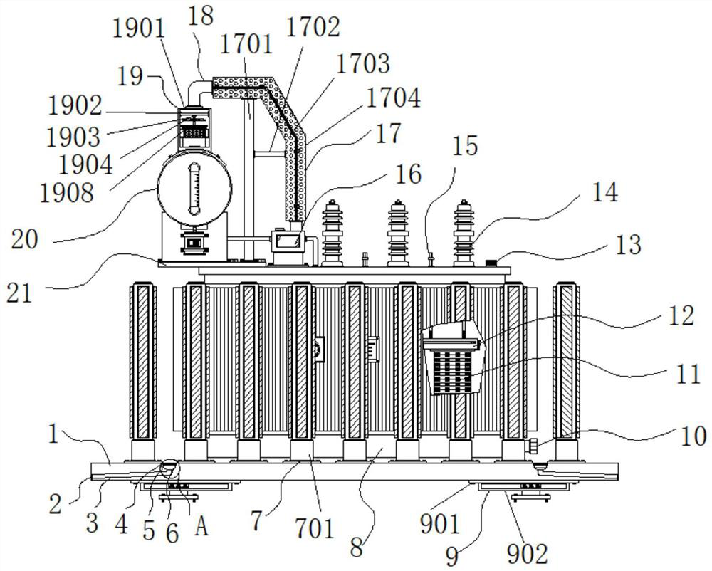
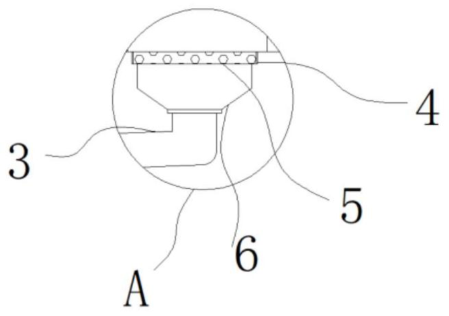
[0035] Example 1: See Figure 1-6, an intelligent transformer, comprising a plate body 1, an oil tank 8 is fixedly connected to the top of the plate body 1, an oil discharge valve 10 is fixedly connected to the bottom end of one side of the oil tank 8, a coil 11 is arranged inside the oil tank 8, and the top of the coil 11 An iron core 12 is fixedly connected, a tap changer 13 is provided on one side of the top of the fuel tank 8, two sets of low-pressure bushings 15 are fixedly connected to the top of the fuel tank 8, three sets of high-voltage bushings 14 are arranged on the top of the fuel tank 8, and the other top of the fuel tank 8 One side is provided with a gas relay 16, the specific model of the gas relay 16 can be QJ1-80TH, the other side of the top of the fuel tank 8 is fixedly connected with a support plate 21, and one side of the top of the support plate 21 is fixedly connected by a fixing piece There is an oil pillow 20, a ceramic explosion-proof pipe 18 is fixedl...

Embodiment 2

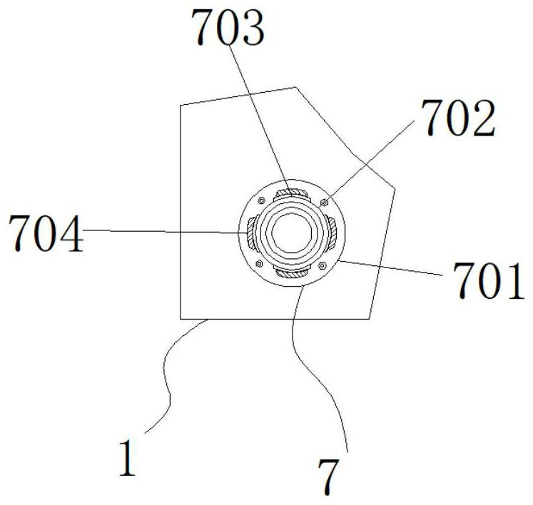
[0039] Embodiment 2: The top of the board body 1 is provided with multiple sets of external impact-proof structures 7, the external shock-proof structures 7 are composed of a base 701, a fixed column 702, a mounting groove 703 and a rubber protective strip 704, and the base 701 is fixedly connected to the board body 1 The top of the base 701 is plugged with a fixed column 702, the front and rear ends and the left and right sides of the fixed column 702 are respectively provided with installation grooves 703, and the inside of the installation groove 703 is fixedly connected with a rubber protective strip 704;

[0040] The bases 701 are arranged at equal intervals;

[0041] Specifically, such as figure 1 and figure 2 As shown, when an external shock comes, the densely distributed fixed columns 702 will block the external impact objects, avoiding direct contact with the fuel tank 8, causing the oil tank 8 to be damaged and leaking oil, causing accidents. The rubber protective...

Embodiment 3

[0042] Embodiment 3: Both sides of the bottom end of the plate body 1 are respectively provided with an adjustable fixed structure 9, and the adjustable fixed structure 9 is composed of a base plate 901, an adjustment groove 902, an adjustment block 903, a roller 904, a connecting block 905, a fixed plate 906 and a fixing bolt 907, the base plate 901 is fixedly connected to one side of the bottom of the plate body 1, the bottom end of the base plate 901 is fixedly connected with an adjustment groove 902, the inside of the adjustment groove 902 is provided with an adjustment block 903, and the inside of the front and rear ends of the adjustment block 903 are respectively connected with three The group roller 904, the bottom end of the adjustment block 903 is fixedly connected with a connection block 905, the connection block 905 runs through the bottom end of the adjustment groove 902 and is fixedly connected with a fixing plate 906, and the two sides of the top of the fixing pla...


PUM


Abstract

The invention particularly relates to the technical field of transformers and discloses an intelligent transformer. The intelligent transformer comprises a plate body, an oil tank is fixedly connected to the top end of the plate body, adjustable fixing structures are arranged on the two sides of the bottom end of the plate body respectively, a pipeline protection structure is arranged on the other side of the top end of a supporting plate, and an oil filtering structure is arranged at the top end of an oil conservator. A ceramic explosion-proof pipe is fixedly connected between the top end of the oil filtering structure and the top end of the oil tank, and drainage and water guide structures are arranged in the two sides of the plate body respectively. According to the actual width of the installation position, the whole equipment is hoisted, a fixing plate is pushed, kinetic energy is transmitted through a connecting block, an adjusting block is driven to move in an adjusting groove, the friction force between the adjusting groove and the adjusting block is reduced through rolling wheels, operation of the equipment is smoother, when the equipment is adjusted to the proper position, fixing installation can be conducted by screwing down fixing bolts, a base plate provides stable installation for the whole structure, and the function of adjusting the installation position is achieved.

Description

technical field [0001] The invention relates to the technical field of transformers, in particular to an intelligent transformer. Background technique [0002] With the advancement of science and technology and the development of society, especially since the electrical revolution, electricity, as the main energy source for human production and life, has filled every corner of modern social life. Relevant equipment, such as transformers, etc., with the passage of time and the continuous change of application scenarios, the traditional transformers are becoming more and more stretched in function and need to be improved. [0003] In the process of realizing the present invention, the inventors have found that at least the following problems in the prior art have not been resolved: [0004] (1) The traditional intelligent transformer has a flat bottom surface, which is prone to water accumulation in rainy weather, which accelerates the corrosion of the bolts and boxes where t...

Claims


Application Information

Patent Timeline
Patent Type & Authority Applications(China)
IPC IPC(8): H01F27/00H01F27/14B08B1/04
CPCH01F27/00H01F27/14B08B1/04
Inventor 刘兵
Owner 刘兵
Why Eureka
Try Eureka