Clamping device and power distribution information transmission device
A technology for information transmission and snap-in slots, which is applied in the field of snap-in devices and power distribution information transmission devices, and can solve problems such as cumbersome operations and poor connection stability
- Summary
- Abstract
- Description
- Claims
- Application Information
AI Technical Summary
Problems solved by technology
Method used
Image
Examples
Embodiment 1
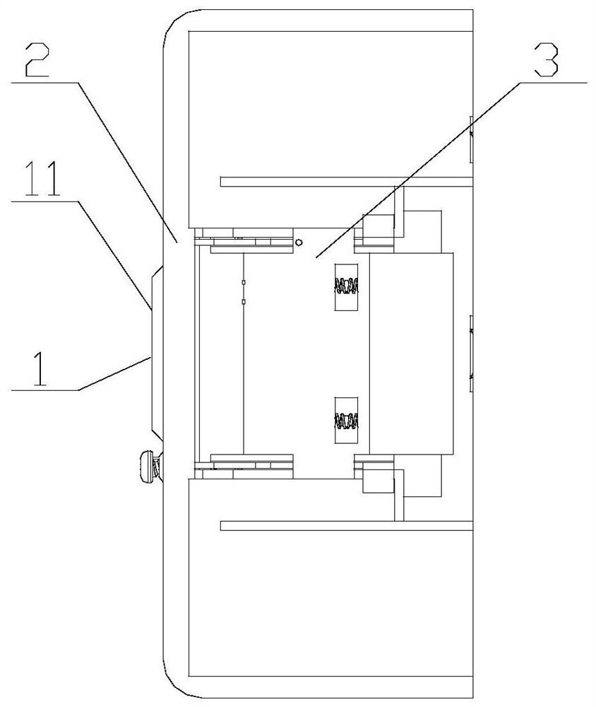
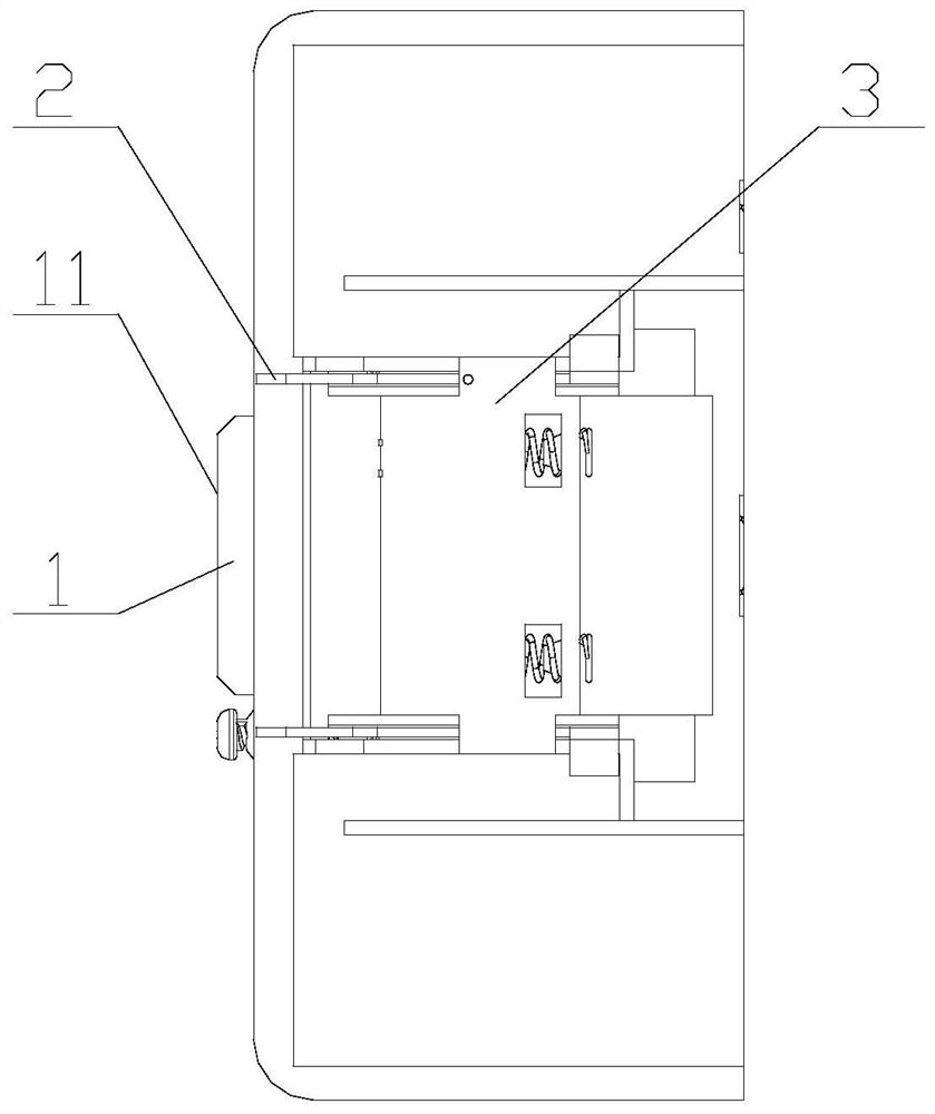
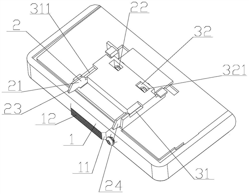
[0042] Such as Figure 1-Figure 6 As shown, the embodiment of the present invention provides a clamping device, including a control piece 1, a clamping piece 2 and a limit seat 3; the control piece 1 is connected to the limit seat 3, and the clamping piece 2 is set at the limit On the seat 3; the control member 1 can control the position of the limit seat 3, so that the clamping member 2 on the limit seat 3 at least includes a retracted state under force and a protruding state without force.
[0043] Specifically, the fast clamping of the split parts of the power distribution information transmission device is realized through the clamping device. Only when the control part 1 is under force during assembly can the retraction of the clamping part 2 be controlled, and the split device can be quickly matched. Assemble the body. After the assembly is in place, remove the force on the control part 1. The control part 1 can realize the protruding and clamping state of the clamping p...
Embodiment 2
[0070] The present invention provides a power distribution information transmission device, including the above-mentioned clamping device and the first split device 4; the first split device 4 is provided with a groove 41 and a clamping groove 42; the control member 1 protrudes Outside the groove 41 , the engaging member 2 can protrude from the engaging groove 42 .
[0071] Specifically, the clamping device is installed on the first split device 4, that is, the control member 1 protrudes from the convex groove on the first split device 4, and the limit seat 3 is close to the inner side of the first split device 4 Installation, that is, the control part 1 and the clamping part 2 are installed inside the first split device 4 .
[0072] Wherein, the control member 1 on the outside of the first split device 4 is subjected to an applied external force, and controls the limit seat 3 to move inward, that is, the clamping member 2 moves inward at the position of the clamping groove 42...
PUM
 Abstract
Description
Claims
Application Information
 - R&D Engineer
- R&D Manager
- IP Professional
- Industry Leading Data Capabilities
- Powerful AI technology
- Patent DNA Extraction
Browse by: Latest US Patents, China's latest patents, Technical Efficacy Thesaurus, Application Domain, Technology Topic, Popular Technical Reports.
© 2024 PatSnap. All rights reserved.Legal|Privacy policy|Modern Slavery Act Transparency Statement|Sitemap|About US| Contact US: help@patsnap.com


