Connecting structure for seat body and working head of electric tool and electric tool

A connection structure and electric tool technology, which is applied in the direction of manufacturing tools and portable mobile devices, etc., can solve the problems of single function of electric tools and poor matching of electric tools, and achieve the effects of easy promotion, ensuring connection stability, and fast clamping

Pending Publication Date: 2021-06-29
启东市宝发机电科技有限公司
View PDF0 Cites 2 Cited by
  • Summary
  • Abstract
  • Description
  • Claims
  • Application Information

AI Technical Summary

Problems solved by technology

[0002] Electric tools generally include electric wrenches, angle grinders, electric chain saws, saber saws, electric impact drills, and electric grinders, etc. However, the seat body and working head of current electric tools are usually fixed by multiple screws and welded, so multiple The matching between different types of power tools is poor, and they cannot be used in common with each other. Each power tool has a single function. If a power tool seat is provided, it can be equipped with working heads with different functions, and quickly achieve a stable connection. Connecting structure and electric tools are bound to be strongly welcomed by the market

Method used


Image

  • Connecting structure for seat body and working head of electric tool and electric tool
  • Connecting structure for seat body and working head of electric tool and electric tool
  • Connecting structure for seat body and working head of electric tool and electric tool

Examples


Embodiment approach

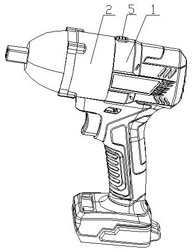
[0027] Such as figure 1 It shows the first embodiment of the connection structure between the power tool base and the working head in the present invention. The power tool base and the working head are detachably connected through the connection structure. The connection structure includes placing the working head 2 close to The two corresponding projections 3 on the side end surface of the seat body 1 also include two card slots 4 placed on the side end surface of the seat body 1 close to the working head 2 and a limit card placed on the side end surface of the seat body 1 close to the working head 2 Block 5, the position limiting card block 5 is placed between the two card slots 4, and the two protrusions 3 are matched with the two card slots 4;

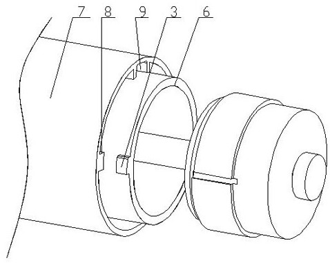
[0028] Such as image 3 As shown, the side of the working head 2 close to the seat body 1 has an inner ring body 6 and an outer ring body 7, and there are a plurality of connecting columns 8 between the inner ring body 6 and the o...

Embodiment 2

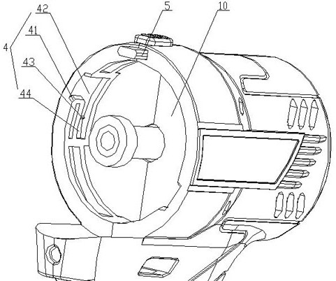
[0036] Such as Figure 4 Shows the second embodiment of the present invention, both sides of the bump 3 have elastic pieces 11, when the bump 3 snaps into the cavity 44 formed by the limit bar 43 and the inner wall of the L-shaped recess 42, the bump 3 The elastic sheet 11 on one side of the block 3 is in close contact with the L-shaped recess 42 , and the elastic sheet 11 on the other side of the protruding block 3 encloses the limiting strip 43 in the elastic sheet 11 .

[0037] Further, the elastic piece 11 includes a longitudinal portion 111 fixedly connected to the side end surface of the protrusion 3, a circular arc portion 112 placed at the upper end of the longitudinal portion 111, and an inclined portion 113 placed at one end of the circular arc portion 112. The opening of the circular arc portion 112 It is arranged downward and smoothly transitions the longitudinal part 111 and the inclined part 113. The limit bar 43 is clamped between the inclined part 113 and the l...


PUM


Abstract

The invention relates to a connecting structure for a seat body and a working head of an electric tool. The seat body and the working head of the electric tool are detachably connected in a replaceable manner through the connecting structure, and the connecting structure comprises two correspondingly-arranged protruding blocks arranged on the side end faces, close to the seat body, of the working head; two clamping grooves formed in the side end face, close to the working head, of the seat body and a limiting clamping block arranged on the side end face, close to the working head, of the seat body are further included, the limiting clamping block is arranged between the two clamping grooves, and the two protruding blocks are correspondingly matched with the two clamping grooves; and an inner ring body and an outer ring body are arranged at the side, close to the seat body, of the working head, a plurality of connecting columns are arranged between the inner ring body and the outer ring body, a cavity allowing the limiting clamping block to be axially embedded is formed between every two adjacent connecting columns arranged close to the limiting clamping block, and the two protruding blocks are correspondingly arranged at the edge position of the side end face of the inner ring body. The connecting structure has the following advantages that the seat body can be quickly matched and connected with various working heads with different functions through the connecting structure, so that the multi-functionalization of the electric tool is quickly realized.

Description

Technical field: [0001] The invention belongs to the field of electric tools, and in particular relates to a connection structure between a seat body and a working head of an electric tool and the electric tool. Background technique: [0002] Electric tools generally include electric wrenches, angle grinders, electric chain saws, saber saws, electric impact drills, and electric grinders, etc. However, the seat body and working head of current electric tools are usually fixed by multiple screws and welded, so multiple The matching between different types of power tools is poor, and they cannot be used in common with each other. Each power tool has a single function. If a power tool seat is provided, it can be equipped with working heads with different functions, and quickly achieve a stable connection. Connection structures and power tools are bound to be strongly welcomed by the market. Invention content: [0003] The purpose of the present invention is to overcome the ab...

Claims


Application Information

Patent Timeline
Patent Type & Authority Applications(China)
IPC IPC(8): B25F5/00
CPCB25F5/00
Inventor 施勇
Owner 启东市宝发机电科技有限公司
Why Eureka
Try Eureka