Tunable stacked plate vibration isolator

a metal plate and vibration isolator technology, applied in the direction of vibration suppression adjustment, shock absorber, spring/damper, etc., can solve the problems of affecting the performance of the electronic component itself and the attached elements, affecting the performance of the electronic component, and causing the vibration of the entire system to be generated. , to achieve the effect of compact size and reducing the vibration of the electrical componen

Inactive Publication Date: 2007-11-20
ARMY US SEC THE
View PDF22 Cites 15 Cited by
  • Summary
  • Abstract
  • Description
  • Claims
  • Application Information

AI Technical Summary

Benefits of technology

[0011]Furthermore, in another embodiment, the invention provides a method for reducing vibrations in an electrical component of an artillery shell, wherein the method comprises stacking a plurality of metal plates, attaching the metal plates to the electrical component, creating vibrations in the artillery shell, and damping the vibrations transmitted to a mounted electronic component by moving the metal plates frictionally opposed to one another. Additionally, the method further comprises retaining the metal plates using a clamp, adjusting a force holding the metal plates together using the clamp, controlling an amount of friction produced by movement of the metal plates using the clamp, and controlling an amount of friction produced by movement of the metal plates using the choice of plate material and a machined surface finish on the surfaces of the metal plates, wherein the metal plates are dimensioned and configured to generate a specific frequency response to the input vibration.
[0012]There are several advantages achieved by the novel aspects of the invention. Specifically, the advantages of the invention include, but are not limited to, the invention's complete reliance on metal components without the use of elastomers, its compact size, and its tunability. The invention is tuned by adjusting the relationship between parts by varying the torque on the clamp screws, which are part of the retaining mechanism. Moreover, the multi-functionality of the invention is also advantageous, because while a preferred embodiment of the invention is to implement a vibration isolator for use in reducing vibrations in an electrical component in an artillery shell, the invention may also be used for the vibrational isolation of any component in a high frequency vibration environment. Other high frequency environments include, but are not limited to, vehicle ballistic shock, armored vehicle main gun firing, vehicle subjected to mine blast, payload during spacecraft launch, item dropped on a hard floor, and payload in any sort of vehicle.

Problems solved by technology

Generally, vibration isolation optimization involves reducing the magnitudes of acceleration transmitted from moving components of devices, machines, structural systems, mountings, etc. to supporting devices, structures, and foundations, etc.[1] Similarly, vibration isolation optimization involves reducing the support motion transmitted to instruments, equipment, or peripheral devices of an overall system.[1] When the forces generated by moving components of a system are transmitted to other components (instruments, etc.) in the system, undesirable vibrations are often generated in the entire system, wherein instruments and equipment can malfunction and suffer extreme damage through failure if not properly isolated from the vibration source.[1] Usually, vibration isolators use elastic material such as cork, rubber, urethane, or neoprene to provide damping to the system.[2]
The electronic components in an artillery shell are often subjected to significant vibrational energy, which causes deleterious effects on the electronic component itself and attached elements.
However, these conventional devices are not easily tunable without additional machining and, in fact, often require complex machining.
Moreover, many of these conventional devices use elastomers.
Unfortunately, the use of elastomers introduces significant temperature dependence for efficient performance.
Such extreme temperature requirements often result in degradation of the vibration isolator when operated over a wide temperature range or of the electronic component itself.

Method used


Image

  • Tunable stacked plate vibration isolator
  • Tunable stacked plate vibration isolator
  • Tunable stacked plate vibration isolator

Examples


Embodiment Construction

[0021]The invention and the various features and advantageous details thereof are explained more fully with reference to the non-limiting embodiments that are illustrated in the accompanying drawings and detailed in the following description. It should be noted that the features illustrated in the drawings are not necessarily drawn to scale. Descriptions of well-known components and processing techniques are omitted so as to not unnecessarily obscure the invention. The examples used herein are intended merely to facilitate an understanding of ways in which the invention may be practiced and to further enable those of skill in the art to practice the invention. Accordingly, the examples should not be construed as limiting the scope of the invention.

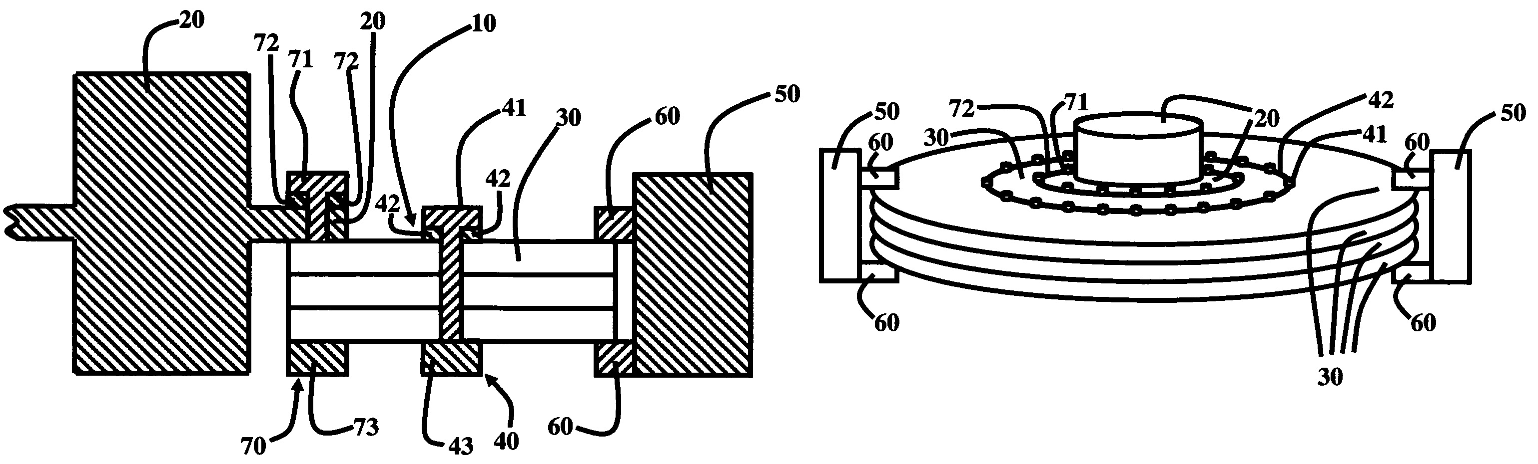
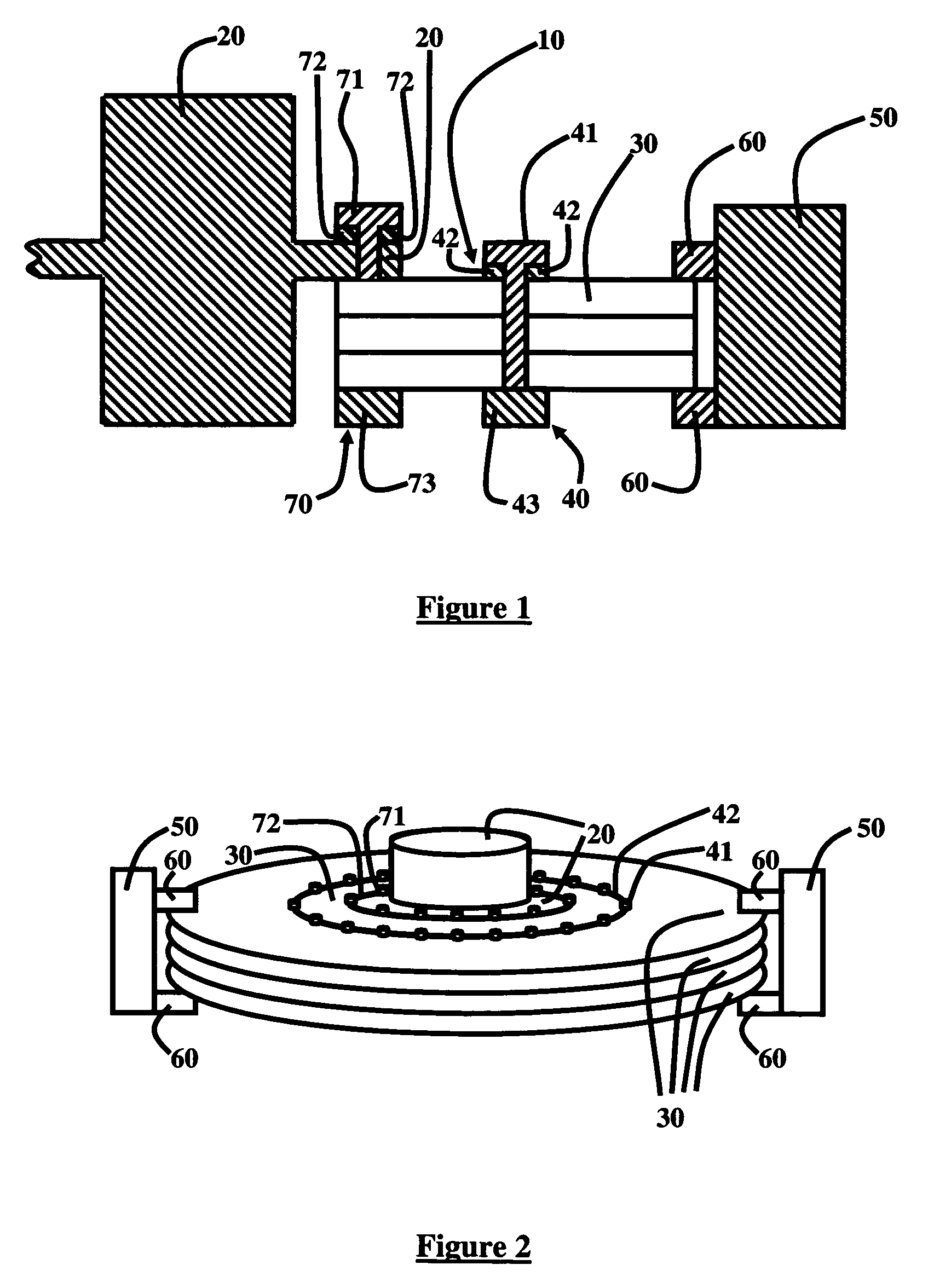
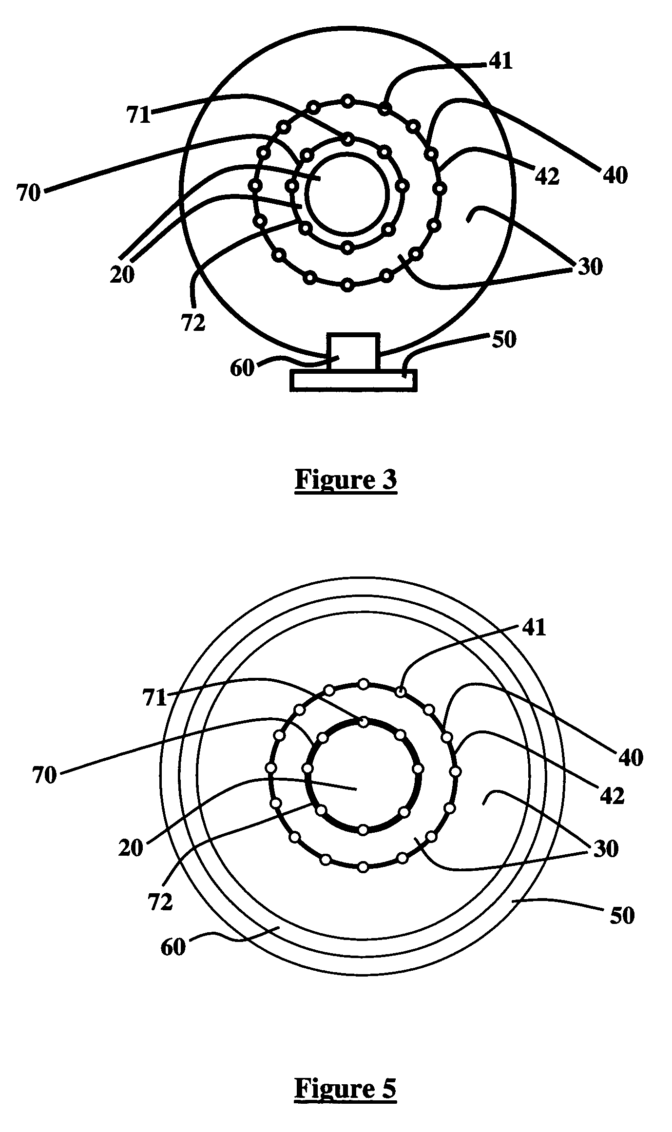
[0022]As previously mentioned, there is a need for a novel vibration isolator device, which does not use elastomers, is compactly sized, and is easily tunable. Referring now to the drawings, and more particularly to FIGS. 1 through 5, ther...


PUM


Abstract

Disclosed is a method and apparatus for reducing vibrations in an electrical device, wherein the apparatus comprises a plurality of stacked metal plates, wherein the stacked metal plates move frictionally opposed to one another upon excitation of the device, and wherein movement of the stacked metal plates produces damping of the vibrations. The apparatus further comprises a clamp retaining the stacked metal plates, and a plurality of retaining mechanisms, wherein the clamp adjusts a force holding the stacked metal plates together, and wherein the clamp controls an amount of friction produced by the movement of the stacked metal plates. Also, the surfaces of the stacked metal plates comprise a machined surface finish, wherein the machined surface finish controls an amount of friction produced by the movement of the stacked metal plates. Moreover, the stacked metal plates are dimensioned and configured to control a frequency response of the vibrations.

Description

GOVERNMENT INTEREST[0001]The invention described herein may be manufactured, used, and / or licensed by or for the United States Government.BACKGROUND OF THE INVENTION[0002]1. Field of the Invention[0003]The invention generally relates to vibration isolators, and more particularly to a tunable stacked metal plate vibration isolator used for damping vibrations in an electrical device.[0004]2. Description of the Related Art[0005]Within this application several publications are referenced by Arabic numerals within brackets. Full citations for these publications may be found at the end of the specification immediately preceding the claims. The disclosures of all these publications in their entireties are hereby expressly incorporated by reference into the present application for the purposes of indicating the background of the invention and illustrating the general state of the art.[0006]Generally, vibration isolation optimization involves reducing the magnitudes of acceleration transmitt...

Claims


Application Information

Patent Timeline
Patent Type & Authority Patents(United States)
IPC IPC(8): F16F7/08F16F7/01F16F15/02F16F7/00
CPCF16F7/023
Inventor BERMAN, MORRIS S.
Owner ARMY US SEC THE
Why Eureka
Try Eureka