Optical fiber sensor mounting structure of natural gas pipeline leakage optical fiber monitoring system

A fiber optic sensor and natural gas pipeline technology, which is applied in the pipeline system, application of light to test fluid tightness, gas/liquid distribution and storage, etc., can solve the problem of unstable installation and connection of fiber optic sensors, leakage fiber optic monitoring system, and single snap-in locking And other problems, to achieve the effect of stable installation structure, convenient use and convenient operation of optical fiber sensor

Inactive Publication Date: 2018-10-16
北京鼎翰科技有限公司
View PDF0 Cites 2 Cited by
  • Summary
  • Abstract
  • Description
  • Claims
  • Application Information

AI Technical Summary

Problems solved by technology

Throughout the various pipeline leakage monitoring technologies at home and abroad, the current commonly used negative pressure wave method, flow balance method, pressure slope and other oil pipeline leakage detection technologies cannot effectively solve the problem of gas pipeline leakage detection, especially for Identification and positioning of tiny leaks; and the current installation structure of optical fiber sensors cannot have multiple snap-in locking effects, resulting in unstable installation and connection of optical fiber sensors, which in turn affects the user's use effect
[0003] Therefore, it is urgent to design an optical fiber sensor installation structure for a natural gas pipeline leakage optical fiber monitoring system to solve the problem of insufficient stability of the installation connection and single snap-in locking in the prior art

Method used


Image

  • Optical fiber sensor mounting structure of natural gas pipeline leakage optical fiber monitoring system
  • Optical fiber sensor mounting structure of natural gas pipeline leakage optical fiber monitoring system
  • Optical fiber sensor mounting structure of natural gas pipeline leakage optical fiber monitoring system

Examples


Embodiment

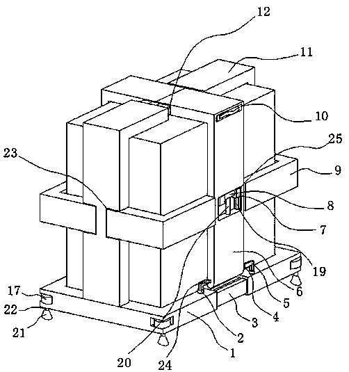
[0020] An optical fiber sensor installation structure for a natural gas pipeline leakage optical fiber monitoring system, including support frames 1 installed on both sides of the optical fiber sensor, two support frames 1 are clamped on the lower side of the optical fiber sensor, and both ends of the support frame 1 are provided with a second A rack bar 3 , the two ends of the support frame 1 are also provided with first slots 30 , and the first slots 30 are located on one side of the first rack bar 3 .

[0021] Rotation is connected with gear 16 in the first slot 30, and one end of gear 16 is connected with rotation bar 2, and the top of support frame 1 is provided with the rotation opening that communicates with first slot 30, and one end of rotation bar 2 passes through rotation opening, One end of the first rack bar 3 away from one of the support frames 1 is inserted into the first slot 30 of the other support frame 1, and one side of the first rack bar 3 is meshed with th...


PUM


Abstract

The invention discloses an optical fiber sensor mounting structure of a natural gas pipeline leakage optical fiber monitoring system. The structure comprises supporting frames which are arranged on the two sides of the optical fiber sensor, the two supporting frames are connected on the side face of the lower portion of the optical fiber sensor in a clamped mode, the two ends of the supporting frames are correspondingly provided with first rack rods, first inserting grooves are formed in the two ends of the supporting frames, and the first inserting grooves are located on one sides of the first rack rods; gears are rotationally connected in the first inserting grooves, one ends of the gear are connected with rotating rods, and rotating openings communicating with the first inserting grooves are formed in the upper portion of the supporting frames; and one ends of the rotating rods penetrate through the rotating openings, and one end, away from one of the supporting frames, of the firstrack rod is inserted into the first inserting groove of the other supporting frame. According to the structure, triple locking and clamping-connecting effects are achieved, one layer is connected toanother layer in a clamped mode, so that the optical fiber sensor mounting structure of the natural gas pipeline leakage optical fiber monitoring system can be more stable, and the invention providesthe optical fiber sensor mounting structure of the natural gas pipeline leakage optical fiber monitoring system.

Description

technical field [0001] The invention relates to the technical field of an optical fiber sensor installation structure, in particular to an optical fiber sensor installation structure of a natural gas pipeline leakage optical fiber monitoring system. Background technique [0002] At present, the total length of pipelines built in the world has reached 2.5 million kilometers, which has surpassed the total mileage of railways and has become the main mode of energy transportation in the world. Oil transportation in developed countries and oil-producing regions in the Middle East has all realized pipelines. Throughout the various pipeline leakage monitoring technologies at home and abroad, the current commonly used negative pressure wave method, flow balance method, pressure slope and other oil pipeline leakage detection technologies cannot effectively solve the problem of gas pipeline leakage detection, especially for Identification and positioning of tiny leaks; and the current...

Claims


Application Information

Patent Timeline
Patent Type & Authority Applications(China)
IPC IPC(8): F17D5/02G01M3/38
CPCF17D5/02G01M3/38
Inventor 董晶龙
Owner 北京鼎翰科技有限公司
Why Eureka
Try Eureka