Treatment auxiliary device for traditional Chinese medicine gastroenterology department
A technology of gastroenterology and auxiliary devices, applied in physical therapy, massage auxiliary products, kneading massage equipment, etc., can solve the problems of increasing patients' discomfort, low degree of expansion, and insufficient massage, and achieve the goal of massaging. Flexible and changeable, increase adaptability, and reduce dead angle positions
- Summary
- Abstract
- Description
- Claims
- Application Information
AI Technical Summary
Problems solved by technology
Method used
Image
Examples
Embodiment 1
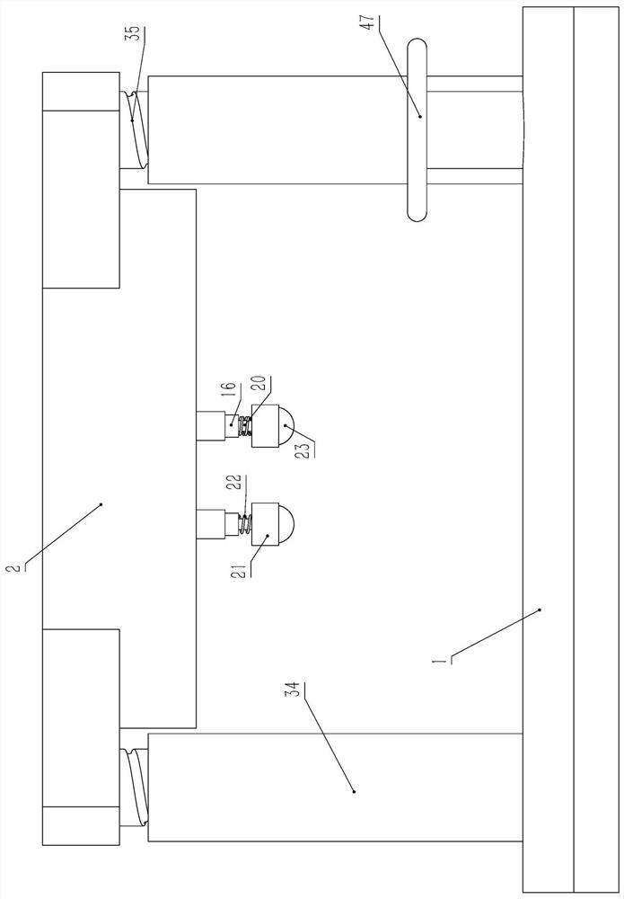
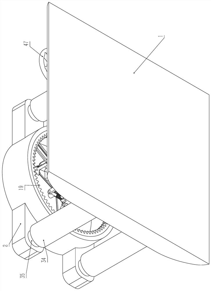
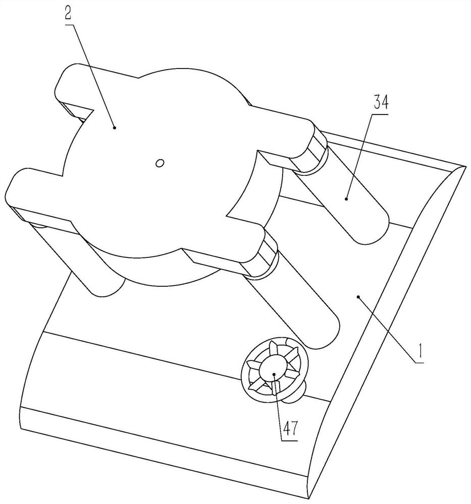
[0027]Embodiment 1, a therapeutic auxiliary device for gastroenterology in traditional Chinese medicine, including a support shell 1, an installation shell 2 is arranged above the support shell 1, a lifting mechanism is connected between the installation shell 2 and the support shell 1, and the lower end of the installation shell 2 is designed to be open , the mounting shell 2 is fixed with a vertical central shaft 3 placed in the mounting shell, the lower end of the central shaft 3 is covered with an inherent central gear 4, the rotating sleeve on the central shaft 3 is provided with a shaft sleeve 5, and the shaft sleeve 5 is placed on the central gear Above 4, the shaft sleeve 5 is covered with an inherent rotating disk 6, and the rotating disk 6 is fixed with a plurality of slide rails 7 evenly distributed along the circumferential direction of the central gear 4. The slide rails 7 are arranged radially along the central gear 4, and the slide rails 7 is fitted with a slidin...
Embodiment 2
[0032] Embodiment 2, on the basis of Embodiment 1, the massager includes a probe rod 20 vertically slidably connected to the sliding shaft 16 (specifically, there is a probe rod 20 inside the sliding shaft 16 that is coaxial with the sliding shaft 16 and penetrates downward. The sliding hole of the sliding shaft 16, the sliding hole slides through the coaxial probe rod 20 of the sliding shaft 16). The return spring 22 set on the probe rod 20, the massage ball 23 is rolled and installed on the massage ball shell 21, and the part of the massage ball 23 contained in the massage ball shell 21 exceeds half of the massage ball 23 as a whole. This design makes the massage ball 23 only rolls relative to the massage ball shell 21, and will not come out of the massage ball shell 21. When the massager vertically reciprocates and slides, it drives the massage ball 23 to move vertically. When the massage ball 23 moves downward and contacts the abdomen of the human body At this time, the ma...
Embodiment 3
[0033]Embodiment 3, on the basis of Embodiment 1, the inherent deflection gear 24 is set on the rotating shaft 11, the guide rail 25 arranged along the length direction of the slide rail 7 is fixed on the slide rail 7, the two ends of the guide rail 25 are closed, and the guide rail 25 slides Cooperate with the adjustment rack 26 corresponding to the deflection gear 24. In the initial state, the adjustment rack 26 is not meshed with the deflection gear 24, and the adjustment rack 26 is located at the end of the guide rail 25 away from the center gear 4 (that is, the beginning of the stroke). 5. The upper rotation sleeve is provided with a worm wheel 27, and the outer circumference of the worm wheel 27 is evenly distributed with horizontal connecting rods 28 corresponding to a plurality of adjustment racks 26. One end of the connecting rod 28 and the upper surface of the worm wheel 27 are vertically The pin is hinged, the other end of the connecting rod 28 and the adjustment rac...
PUM
 Abstract
Description
Claims
Application Information
 - R&D
- Intellectual Property
- Life Sciences
- Materials
- Tech Scout
- Unparalleled Data Quality
- Higher Quality Content
- 60% Fewer Hallucinations
Browse by: Latest US Patents, China's latest patents, Technical Efficacy Thesaurus, Application Domain, Technology Topic, Popular Technical Reports.
© 2025 PatSnap. All rights reserved.Legal|Privacy policy|Modern Slavery Act Transparency Statement|Sitemap|About US| Contact US: help@patsnap.com


