
Automobile part punching device

A technology of punching device and auto parts, applied in the field of parts punching device, can solve the problems of low automation degree and difficult operation of punching device, and achieve the effect of improving automation degree and fast switching control.

Pending Publication Date: 2021-09-17
张文龙
View PDF13 Cites 0 Cited by
  • Summary
  • Abstract
  • Description
  • Claims
  • Application Information

AI Technical Summary

Problems solved by technology

[0003] However, when the current punching device for auto parts is in use, it is necessary to manually move the punching parts continuously so as to realize the continuous punching operation of the parts by the punching abrasive tool, and when the current punching device is in use, the punching device only It can produce punching parts with the same shape. When changing the punching shape, it is necessary to reinstall and debug the relevant punching abrasives. The operation is difficult, and the automation of the punching device is low.

Method used


Image

  • Automobile part punching device
  • Automobile part punching device
  • Automobile part punching device

Examples


Embodiment Construction

[0027] It should be noted that, in the case of no conflict, the embodiments of the present invention and the features in the embodiments can be combined with each other.

[0028] In describing the present invention, it should be understood that the terms "center", "longitudinal", "transverse", "upper", "lower", "front", "rear", "left", "right", " The orientations or positional relationships indicated by "vertical", "horizontal", "top", "bottom", "inner" and "outer" are based on the orientations or positional relationships shown in the drawings, and are only for the convenience of describing the present invention and Simplified descriptions, rather than indicating or implying that the device or element referred to must have a particular orientation, be constructed and operate in a particular orientation, and thus should not be construed as limiting the invention. In addition, the terms "first", "second", etc. are used for descriptive purposes only, and should not be understood ...


PUM


Abstract

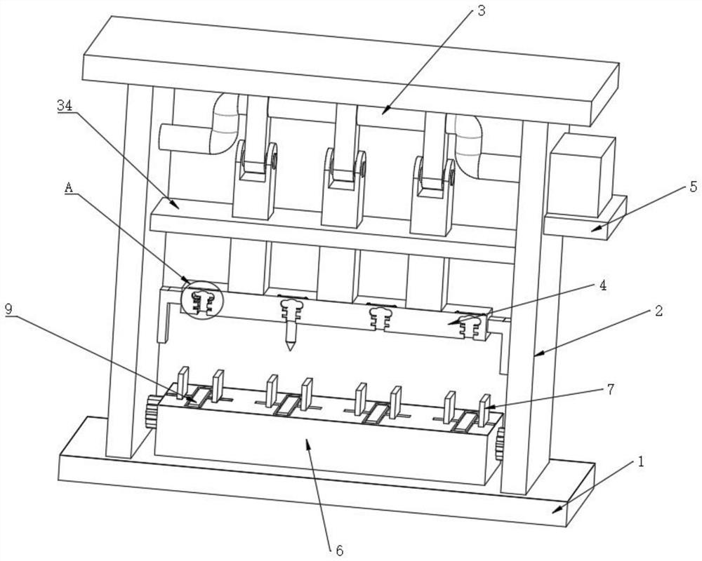
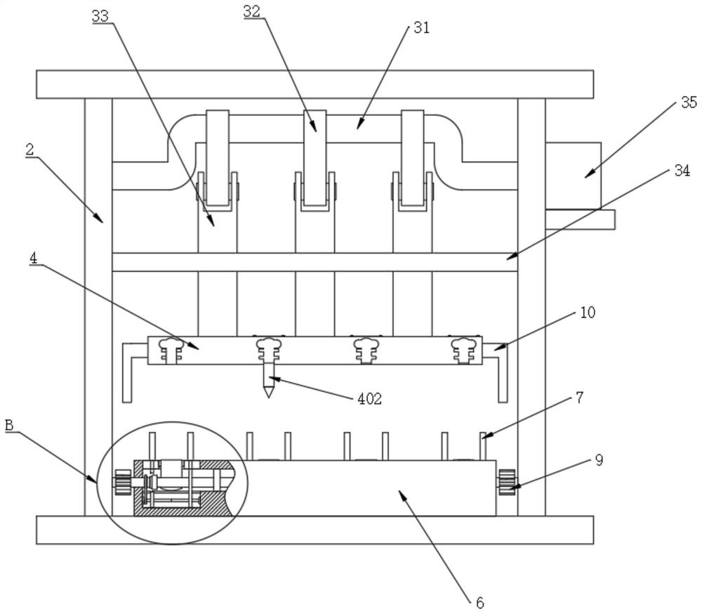
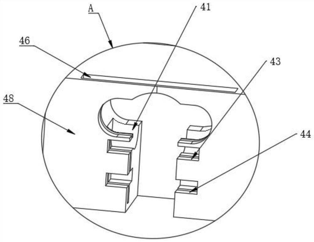
The invention relates to the technical field of part punching devices, in particular to an automobile part punching device which comprises a mounting bottom plate, a plurality of groups of supporting blocks and a workbench, and is characterized by further comprising a punching assembly, a transmission adjusting mechanism and a power assembly, the punching assembly is arranged between the two groups of supporting blocks and used for assembling and disassembling different punching grinding tools, and the punching assembly comprises mounting blocks used for mounting the grinding tools. Through cooperative use of the workbench, the punching assembly, the transmission adjusting mechanism, the power assembly and a toothed plate, when the automobile part punching device is used, corresponding grinding tools on the punching assembly can be selected according to requirements, after the grinding tools are installed, parts needing to be punched are placed on the workbench, and the power assembly can drive the punching assembly, so that the punching grinding tools on the punching assembly make contact with the parts to perform punching operation on the parts, and the automobile part punching device is simple and convenient.

Description

technical field [0001] The invention relates to the technical field of parts punching devices, in particular to a punching device for automobile parts. Background technique [0002] Punching machine is a kind of mechanical equipment that is driven by the power mechanism after the raw materials are installed, and the punching die acts on the material to complete the punching. It is one of the indispensable tools in the production of punching parts. [0003] However, when the current punching device for auto parts is in use, it is necessary to manually move the punching parts continuously so as to realize the continuous punching operation of the parts by the punching abrasive tool, and when the current punching device is in use, the punching device only It can produce punching parts with the same shape. When changing the punching shape, it is necessary to reinstall and debug the relevant punching abrasives. The operation is difficult, and the automation of the punching device ...

Claims


Application Information

Patent Timeline
IPC IPC(8): B21D28/24B21D28/34B21D28/04B21D45/02
CPCB21D28/24B21D28/34B21D28/04B21D45/003
Inventor 张文龙
Owner 张文龙
Learn More